Creating an Animatronic Robot Head (Part 2)
How many ways do you think there are to equip your robot’s eyes with pan-and-tilt functionality?
February 17, 2022

I can’t tell you how fast things are moving at the moment. In my previous column on the topic of creating an animatronic robot head, I explained how this project came to be. First, my chum Steve Manley (who is based in the UK) and your humble narrator (who is based in the USA) decided to create some tricolor LED extravaganzas that we modestly monikered Steve and Max’s Awesome Displays (SMADs).
In my case, I used two SMADs to form the eyes of a “pseudo” robot head that could not move in any way. This is not to say that it wasn’t awesome in its own right, but then someone suggested that things would be made more interesting if I were to add motion into the mix. The original suggestion was for each of the eyes to be able to pan (swing from side to side) and tilt (lean forward and backward) on an individual basis.
I chatted with Steve about this, and he agreed that it would be fun to do something along these lines. Steve and I both invested in a pair of the 4-axis joysticks I discussed in my previous column. I mounted my joysticks on a small wooden platform, while Steve leaped into action and 3D printed a cunning console that -- in addition to the joysticks -- also housed the majority of his electronics (microprocessor, analog multiplexers, etc.).
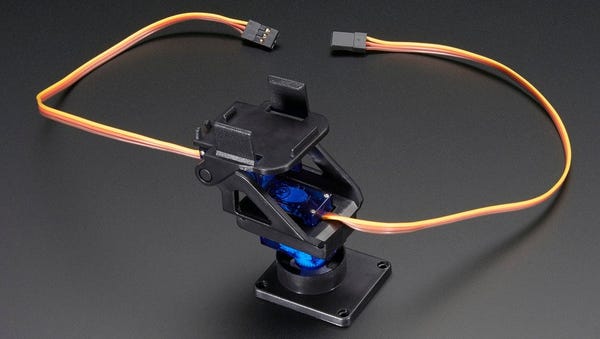
With regard to the pan-and-tilt functionality, I bounced over to the Adafruit website and purchased a pair of pre-assembled Pan-and-Tilt Mechanisms, each of which is equipped with two micro-servos.

As an aside, the “pan” and “tilt” nomenclature I’m using originates with the pan-and-tilt heads upon which movie and television cameras are mounted. These devices allow the camera to be rotated in a horizontal plane (pan) or in a vertical plane (tilt).
Now, this is where things start to get interesting because although Steve and I had discussed what we wanted to do, we hadn’t had a brain-stem-storming session on how to do it. When we look closely at the image above, we see that the pan function -- the servo-driven sub-assembly on the bottom -- is mechanically distinct from the tilt function -- the servo-driven sub-assembly on the top.
To be honest, when it comes to servo-driven pan-and-tilt mechanisms, this is the only way I’ve ever seen these things implemented. By comparison, Steve was unfamiliar with the way things “should be done,” so he went off and created something completely different.
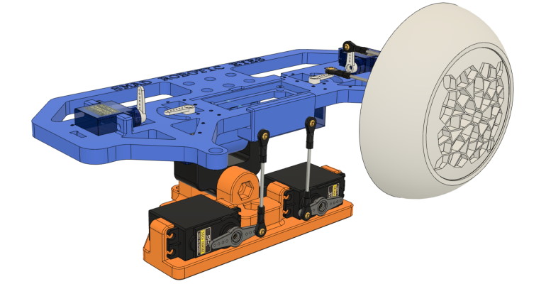
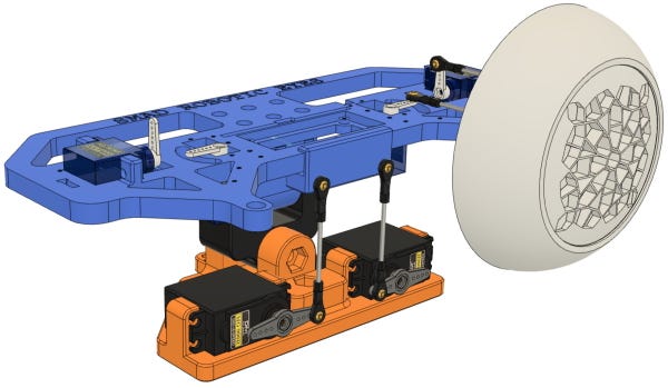
As a starting point, take a look at the image below. Although this isn’t 100% related to our discussion here, let’s begin with the 3D-printed orange assembly at the bottom. This holds two servos that are connected to the 3D-printed blue platform above. Using these two servos, if both are driven up or down, they will tilt the front of the blue platform up and down, respectively. Alternatively, if one of these servos drives up and the other pulls down, the blue platform will lean to one side (like cocking your head by tilting it such that one of your ears gets closer to your shoulder).
What’s not shown here is that the orange assembly will sit on top of the robot’s neck, to which it will be attached via yet another servo that will cause the orange assembly (and the blue platform sitting on top of it) to be panned from side to side.

Returning to the blue platform, this is the part that carries the four servos that control the eyes -- two per SMAD. Only the head’s left SMAD, which appears on the right of this image, is shown here. If you compare this to my pan-and-tilt mechanisms, do you notice anything unusual when you look at the two servos connected to the SMAD? That’s right, unlike the typical arrangement, we don’t have one sitting on top of the other.
When Steve tried to explain how this was going to work, I couldn’t wrap my brain around how one servo could control the pan without affecting the tile while, at the same time, the other servo could control the tilt without affecting the pan. Eventually, Steve created the animation video shown below.
O-M-G! This is brilliant. To be honest, I’ve never seen anything quite like this mechanism before. Furthermore, I’ve shown this video to a number of my engineering friends, and it’s new to them also. All I can say is “color me impressed!”
At the time of this writing, Steve has everything up and running. In fact, he’s created a second head for yours truly. Even better, as I pen these words, my robot head is winging its way across the Atlantic Ocean. I cannot wait to hold my head in my hands (and it’s not often you hear yourself say that). I shall, of course, report further in a future column. In the meantime, as always, I look forward to receiving your comments, questions, and suggestions.
About the Author(s)
You May Also Like


