You start with a simple PCB carrying a few tricolor LEDs, and before you know it you’re working on a fully articulated robot head.
January 3, 2022
There’s an old saying that goes, “Unexpectedly pleasurable events boost dopamine release, which causes your internal clock to run faster” (you may be more familiar with the shorter version: “Time flies when you’re having fun”). Whoever first said this certainly hit the proverbial nail on the head, because I’m currently having so much fun that I don’t seem to have any time left at all.
Earlier this year, I made mention of a project I’m working on with my chum Steve Manley to create a 10-character chronograph using our interpretation of 21-segment Victorian displays.
As you may recall from my earlier column -- Add Victorian Charm with Segment Displays and Nixie Tubes -- a guy called George Lafayette Mason filed a patent for his 21-segment displays in 1898, which explains the “Victorian” moniker. The original versions of these displays employed small incandescent bulbs in each segment, where these bulbs were controlled by a complicated electro-mechanical switch that could activate various groups of segments to represent different alphanumerical characters and symbols as required.
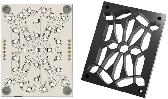
In our case, Steve designed a small circuit board that’s 50 mm wide by 65 mm tall, and that carries 35 WS2812 tricolor LEDs. He also created a 3D printed shell that attaches to the front of the board. It’s this shell that defines the 21 segments. Seven segments boast only one LED, while the other fourteen segments flaunt two LEDs each. In the case of the 2-LED segments, driving the LEDs with different colors can result in some interesting effects. The shell itself is 10 mm thick, which allows the light from the LEDs to spread out, thereby preventing them from appearing as point sources. Also, we attach a diffuser to the front of each shell (we use rectangles cut out of the white plastic separator sheets you can purchase for use with ring binders).
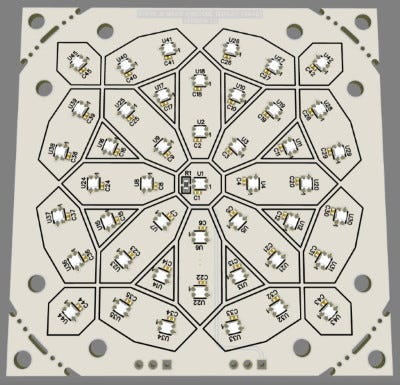
As you can see in this video, which shows two characters displaying a simple starburst effect, the result is rather tasty. The only problem is that these displays are geared up to displaying alphanumeric characters. For a variety of reasons, we wanted something a little more generic, which prompted us to create Steve and Max’s Awesome Displays (SMADs). In this case, we started with an 80 x 80 mm board carrying 45 tricolor LEDs.
Of course, once you have a SMAD in your hands, you have to do something SMAD with it (and that’s not something you expect to hear yourself say daily). One of the things I thought about doing was creating a 25 x 25 array of the little scamps. I can only imagine the effects we could achieve with this bodacious beauty, especially if we decided to make it react to sound. Sad to relate, however, lack of funds prevented me from proceeding further with this idea, so I was forced to turn to something simpler.
My next thought was to create a robot reminiscent of Wall-E with his two big eyes. In my case, I planned on using two of our SMADs for the eyes. My idea was that I could make the SMADs appear to be looking left, right, up, down, and so forth by varying the color and intensity of the various segments.
Unfortunately (or fortunately, depending on your point of view), Steve was busily running amok with his 3D printer. Our original plan was to equip the SMADs with 3D shells, each containing 29 segments. If you look at the silkscreen on the board above, you’ll see that it indicates 13 segments with one LED each and 16 segments with two LEDs each. However, Steve got to wondering what things would look like if he created an alternative shell with 45 segments, each flaunting its LED.
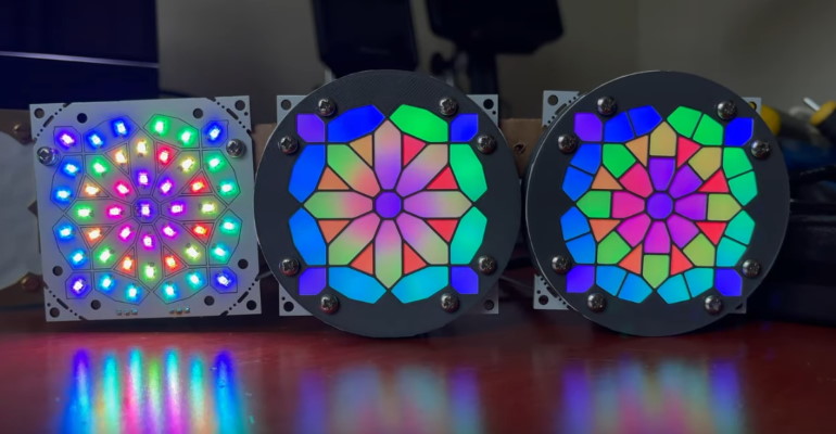
As you can see from this video comparing a bare SMAD (left), a SMAD with a 29-segment shell (middle), and a SMAD with a 45-segment shell (right), the ensuing effects are really, really tasty.
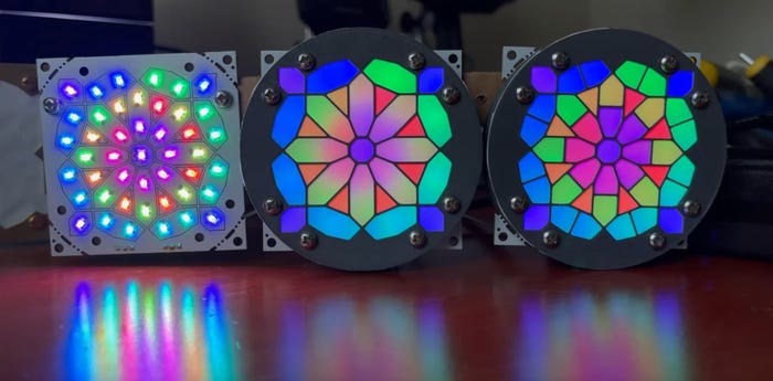
Arrggghhh (and I mean that most sincerely). It’s not that the 45-segment results are unimpressive. The problem is that I was now forced to choose my robot head. Should I stick with two of the original 29-segment shells, or would it be better to opt for two of the new 45-segment shells? This wasn’t an easy decision because both shell types bring something to the party. On the one hand, the 29-segment shells offer beguiling, diffused color effects. On the other hand, SMADs equipped with 45-segment shells provide interesting stained-glass effects (I’m also reminded of a kaleidoscope).
In the end, I did what any self-respecting Max would do, which -- as you can see in the image below -- was to create two robot heads, each sporting a pair of SMAD eyes, with one brandishing 29-segment shells and the other vaunting 45-segment shells (the white box in the foreground is an early card mockup). Ah well, “Two heads are better than one,” as the old saying goes.
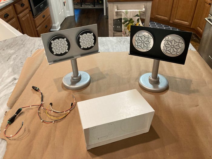
The image above shows the heads in an early stage of development shortly after the front panels were attached. By comparison, the image below presents a closer look at a finished head. The machine screws on the side are just for show; in reality, most of the head parts were attached using my trusty hot glue gun.
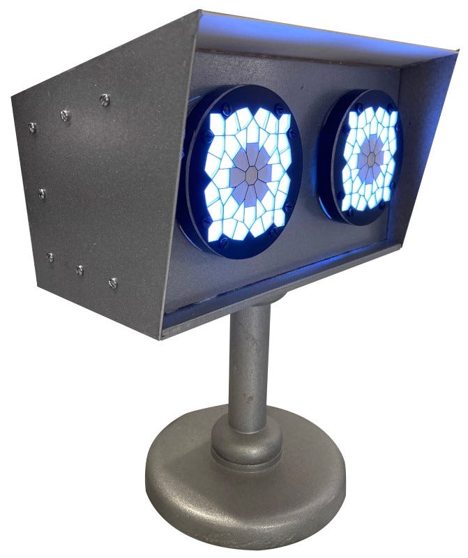
With regard to the base and the supporting column, although these look like metal (well, I hope they do), they are actually formed from bits of scrap wood that I turned on a lathe (see also Just Call Me A Woodworking Fool).
To be honest, I was quite happy with the way these turned out and I’ve been having a lot of fun with them, like getting them to “talk” to each other by flashing messages in Morse code (see this video). But then a friend suggested that it would be much more impressive if the entire head could pan and tilt and if the eyes could also pan and tilt in their own right. As soon as he said this, I started to envisage a platform to which I could attach sensors such that the head could detect your presence and its SMAD eyes could track you as you moved around the room. We could even implement facial recognition and expression detection so the eyes could be green if you smile but turn red if you frown, for example.
So many things to do... so little time to do them all in... How about you? Do you have any SMAD thoughts you’d care to share?
About the Author(s)
You May Also Like


