Easily Add Motion and Orientation Sensing to Improve Your Projects
By means of MEMS sensors and inexpensive breakout boards, it’s easy to add motion and orientation detection to your hobby and professional projects.
April 20, 2021

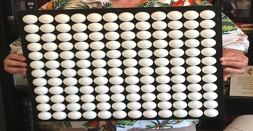
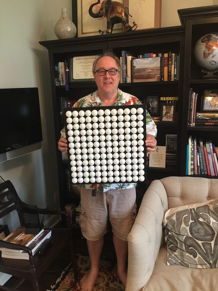
In an earlier column, I introduced my 12x12 ping pong ball array. As you may recall, each of the ping pong balls is equipped with a tricolor LED in the form of a WS2812B. These are commonly known as NeoPixels because that’s the umbrella name for a collection of WS2812B-based products from Adafruit.
In the case of my 12x12 array, I chopped a length of 30-Pixel-Per-Meter NeoPixel Strip into individual segments that I attached to the back of the ping pong balls. This approach worked well for this project and it’s much cheaper than purchasing individually mounted or packaged devices. Adafruit does offer 60- and 144-pixel-per-meter strips, but you end up with much smaller copper pads that are harder to work with when you chop the strip into pieces.
Actually, I originally created a small test rig to evaluate alternative implementations. In the first, I simply attached the NeoPixel directly to the back of the ping pong ball using hot glue. In the second, I cut a 3/8” diameter hole in the back of the ping pong ball so the NeoPixel was effectively mounted inside the ball.
As a word to the wise, don’t try to use an electric drill to create holes in ping pong balls because this will end in tears. A much better approach is to cut the holes using small, curved nail scissors. Also, as I’ve learned to my cost, you should never apply hot glue to NeoPixels that is currently powered up because you may end up with a little tear rolling down your cheek as you watch them “flare and die.” When this happened to me, I initially thought that the glue might conduct while in its liquid state, thereby causing a short circuit. I also considered electrostatic discharge (ESD) as a potential culprit. After wielding my multimeter and consulting with colleagues, however, we decided that the problem was a thermal runaway.
![]()
In the case of this particular project, I opted to use a teeny-tiny Seeeduino XIAO microcontroller (see Say Hello to the XIAO), which costs only around $4.90 and is about the same size as a regular postage stamp. This little beauty, which can be programmed using the Arduino’s integrated development environment (IDE), boasts a 32-bit Arm Cortex-M0+ processor running at 48 MHz with 256 KB of flash memory and 32 KB of SRAM, thereby providing all the resources I need to drive my array. It also supports Adafruit’s NeoPixel library, which is, after all, the point of this particular exercise.

In addition to experimenting with various lighting effects, I’ve also used my array as the display mechanism for a number of applications, such as an implementation of a cellular automaton in the form of Conway’s Game of Life (GOL). Furthermore, I’ve used the array as a visualization tool for a variety of experiments, including motion and orientation detection.
When you were a kid, did you ever have one of those toys that involved a wooden maze with a glass marble or metal ball bearing? The maze was mounted in a wooden box with two knobs on the sides. One knob tilted the maze in a left-right fashion, while the other leaned it forwards or backward. The idea was to use the knobs to guide the ball around the maze without letting it fall through any of the holes.
Well, I decided to implement something like this using my ping pong ball array. The idea is to hold the array horizontally and then use a MEMS motion and orientation sensor to detect when the array is tilted and cause a “ball” (illuminated pixel) to “roll” around.
This is where things start to grow a little confusing because the terminology is all over the place. Let’s start with the fact that we have three axes, which we can think of as X (left and right), Y (up and down), and Z (forward and backward). We can move back and forth along these axes, which therefore gives us three degrees of freedom (3-DOF). We can also rotate around these axes, thereby providing another 3-DOF. The bottom line is that we have only 6-DOF at our disposal, so why do we see adverts for sensors that purport to support 9-DOF or more? As far as I can tell, it’s because doing so makes everyone’s lives easier.
For the purposes of adding motion (which way are we moving) and orientation (which way are we facing) detection to our projects, there are three main sensors of interest. Accelerometers, which detect linear acceleration; gyroscopes, which detect angular rotation; and magnetometers, which detect magnetic fields. All three of these are available in 1-axis, 2-axis, and 3-axis variants. Thus, if you have a sensor solution that encompasses a 3-axis accelerometer, 3-axis gyroscope, and 3-axis magnetometer, then this would commonly (if incorrectly) be referred to as a 9-DOF sensor.
Of course, nothing is simple. For example, using data from these sensors in its raw form can present a task of such complexity that it makes your brain want to leak out of your ears. Also, each type of sensor has its own “gotcha’s,” such as the fact that accelerometers are subject to noise caused by vibration, while gyroscopes can suffer from drift due to the fact that they are constantly performing integration.
The solution is to employ “sensor fusion,” which refers to the act of combining sensory data derived from disparate sources such that the resulting information has less uncertainty than would be possible if the data from those sources were used individually.
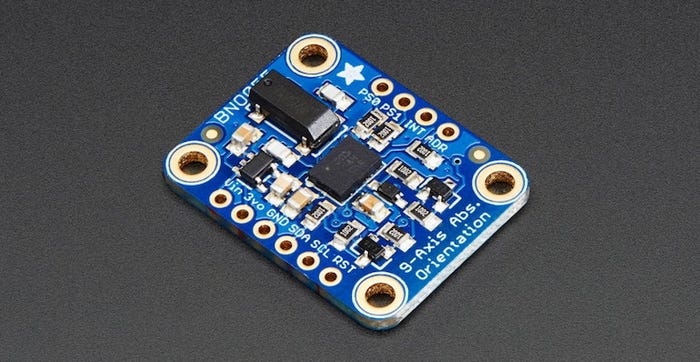
Of course, sensor fusion is itself horrendously complicated and consumes considerable computational power, which is why it’s a good idea to get someone else to do it for you. In my case, I opted to use one of Adafruit’s 9-DOF Fusion breakout boards (BOBs), which features a BNO055 MEMS sensor from Bosch.

In addition to a 3-axis accelerometer, 3-axis gyroscope, and 3-axis magnetometer, the BNO055 also contains a 32-bit Arm Cortex-M0+ processor that performs sensor fusion and – by means of an I2C bus – provides me with motion and orientation data in a form I can use without having to go back to university to earn a Ph.D. Even better, the folks at Adafruit provide example code that literally had me up and running in just a few minutes.
As you can see from this video, my initial tests were reasonably rudimentary. All I currently do is detect a tilt greater than 10 degrees and cause the “ball” to “roll” in the appropriate direction until it runs into a side or corner.
Of course, now that we have our proof-of-concept, the world is our lobster (or shellfish, crustacean, or mollusk of your choice). In the case of the ping pong ball array, my next step will be to model the physics a bit better, like giving the “ball” some sort of “inertia” and making things so increasing the angle of tilt will cause the “ball” to accelerate faster.
Next, I might consider my moving pixel to be a living creature like the head of a snake. Colored pixels representing “food” could randomly appear and disappear. Tilting the array to guide the head of the snake into a food particle could cause the body of the snake to increase by one pixel. Additionally, or alternatively, “hole” pixels could randomly appear and disappear. Hitting one of these could cause our ball or snake to fall into the hole, in which case “Game Over!”
In fact, the more I think about this, the more I realize I can use motion and orientation detection to enhance many of my projects. For example, I’m currently working on a 10-character strip of 21-segment displays. Using my 9-DOF sensor, by tilting my strip, I could cause text to scroll left or right across the display. I will be discussing this more in a future column. In the meantime, I would love to hear your thoughts on how you might augment your own projects with motion and orientation detection capabilities.
Clive “Max” Maxfield received his B.Sc. in Control Engineering from Sheffield Hallam University in England in 1980. He began his career as a designer of central processing units (CPUs) for mainframe computers. Over the years, Max has designed all sorts of interesting “stuff” from silicon chips to circuit boards and brainwave amplifiers to Steampunk Prognostication Engines (don’t ask). He has also been at the forefront of electronic design automation (EDA) for more than 30 years. Already a noted author of over a half-dozen books, Max is always thinking of his next project. He would particularly like to write for teens, introducing them to engineering and computers in a fun and exciting way. This is what sets “Max” Maxfield apart: It is not just what he knows, but how he relates it to the learner.
About the Author(s)
You May Also Like


.jpg?width=300&auto=webp&quality=80&disable=upscale)

