I recently created a 12 x 12 array of ping pong balls, each with a tricolor LED inside, but now I see that rascal Bitluni has built a 1920 ping pong pixel wall!
December 9, 2020

I’m constantly amazed by the way one thing seems to lead to another; also, how things you would assume to be totally disparate oftentimes turn out to be interrelated in weird and wonderful ways.
Yes. You are right. I should provide an example. How shall we start? What’s that you say? “Ping pong balls”? Well, it’s funny you should suggest that as a topic because -- by some strange quirk of fate -- ping pong balls have been much on my mind of late.
This all started deep in the mists of time we used to call early 2019 when I ran across this video of a ping pong ball clock. The idea is that each ping pong ball is illuminated using a tricolor LED.
Prior to this, I’d never really thought about using ping pong balls in this way, but -- as I always say -- “Show me a flashing LED, and I’ll show you a man drooling.”
In this case, the balls have been presented in a hexagonal “honeycomb” arrangement. This has the advantage of keeping any unilluminated areas as small as possible, but it does mean the font is a tad interpretive, as it were.
Of course, when you have a display like this, it’s difficult to restrain yourself to displaying only time. As seen in this video, it’s not long before its creators found themselves experimenting with additional effects.
Once you’ve been exposed to the world of ping pong ball displays, it’s hard to stop yourself from seeking out more. Thus, it wasn’t long before I ran across a guy who goes under the moniker Bitluni and who created a 20 x 15 = 300 ping pong display using WS2828 LEDs. As we see in this video, Bitluni’s display is really rather sharp.
The thing is that I’m easily distracted…. SQUIRREL!!! Thus, it wasn’t long before some other flashing trinket caught my eye and I wandered off to do other things.
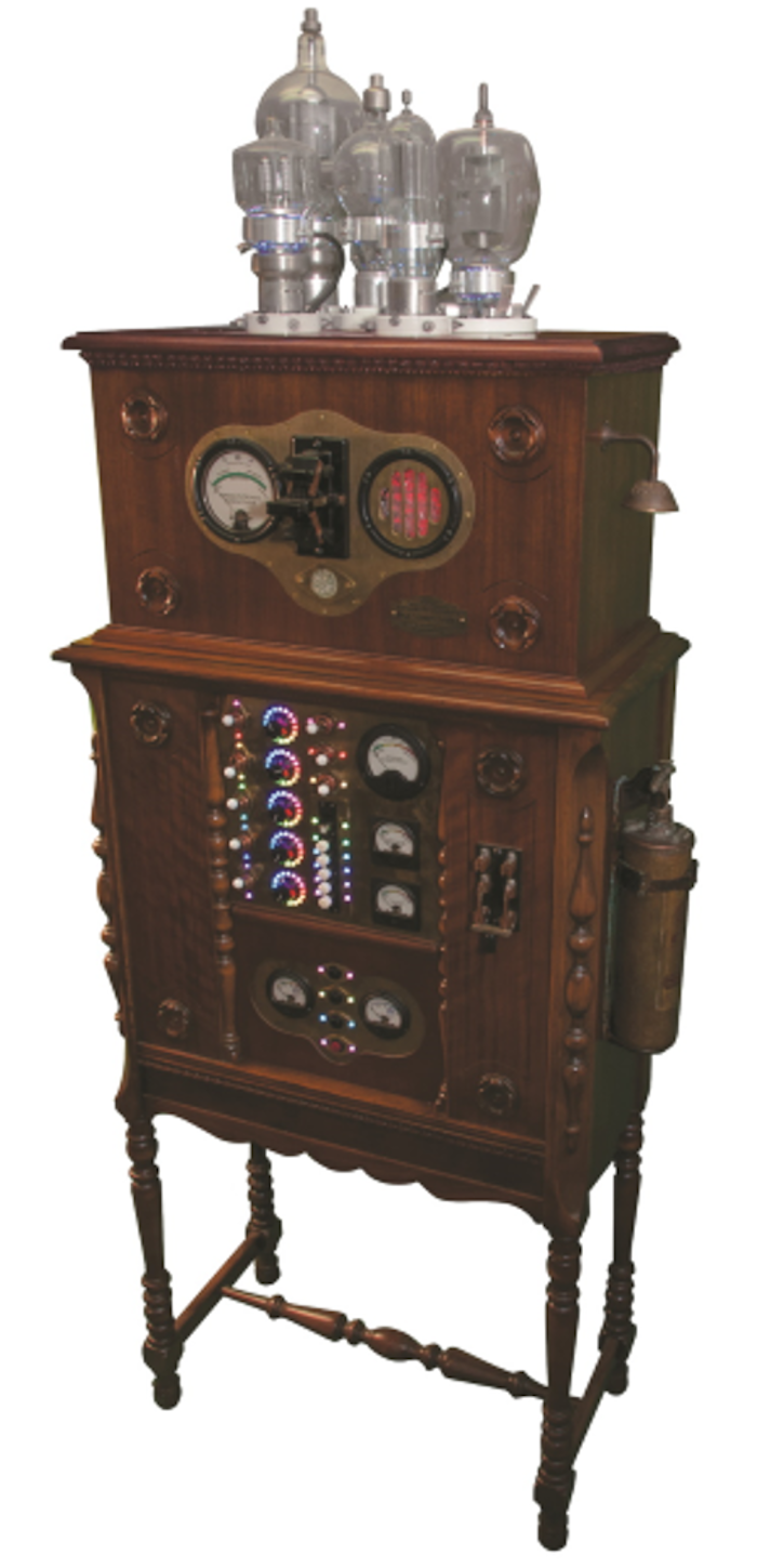
Now, you may or may not know that I write a monthly Cool Beans column for Practical Electronics (PE), which is the UK’s premier electronics, computing, hobbyist, and maker magazine. As fate would have it, earlier this year, I started writing a miniseries of columns on LEDs. Originally, I was intending to focus on the tricolor WS2812 LEDs used in my Prognostication Engine project, but then I got... SQUIRREL!!!
|
The Prognostication Engine. |
I started to ponder the different types of information one could convey, and the different effects one could achieve, using a single throw, single pole (SPST) switch in conjunction with a single unicolor LED. Once I’d started, I couldn’t stop myself. Over the course of a couple of columns, we experimented with SPST switches and single unicolor, bicolor, and tricolor LEDs, followed by SPST switches with dual unicolor, bicolor, and tricolor LEDs.
Next, we moved to consider single-pole, dual throw (SPDT) switches with single and dual unicolor, bicolor, and tricolor LEDs. We also looked at single-pole, center off (SPCO) switches, which are also known as single-pole, changeover switches. These are toggle or rocker switches that behave in an On-Off-On fashion.
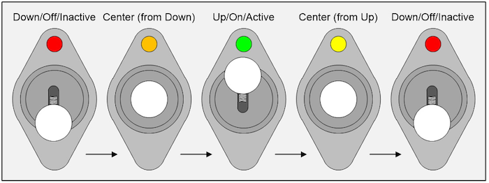
There are all sorts of things we can do with tricolor LEDs. For example, consider using an SPCO switch in conjunction with a single tricolor LED as shown below. In this case, we can use the colors red and green to indicate if the switch is in its inactive or active states, respectively. Also, we can use colors like orange and yellow to indicate that the switch is currently in its center-off-state, with the different colors indicating the switch’s previous state.
|
An SPCO switch with a single tricolor LED. |
Of course, we should note that the convention of a switch in its down position being off and its up position being on is the way things typically work in the USA. It’s the other way around in the UK, and you take your chances in the rest of the world, but we digress.
I must admit that I was amazed by how many emails these articles triggered from around the world. I was especially impressed by the number of folks who said they had been inspired to purchase an Arduino microcontroller development board and start experimenting themselves.
One such message came from a retired engineer called David R. Humrich, who hangs his hat in Perth, Australia, and who ended his first email saying, “I wanted you to know that a whole new world is opening for me and it's all your fault!”
Well, David got his own back a short time later, because he sent a follow-up email saying he’d purchased a 5 x 8 array of WS2812 LEDs and he was wondering what to do with it. As part of my reply, I took this video of a little “Worm” program I’d created yonks ago randomly working its way around an 8 x 8 array here in my office.
Unfortunately, this caused me to start wondering what such a program would look like on a ping pong ball array. In turn, this tempted me to determine how much ping pong balls cost, and I was amazed to discover you could purchase 144 balls for only $11 on Amazon. Of course, these aren’t of a quality you would use to actually play ping pong, but they are perfect for creating LED displays.
Well, it would take a stronger-willed man than your humble narrator to resist a bargain like this, so I immediately ordered two bags (in case I needed spares). I was tempted to build a 15 x 15 = 225 ball array, but I restrained myself to a 12 x 12 = 144 ball prototype, and I’m so glad I did because this took much longer than I’d anticipated. Suffice it to say that if I decide to build a larger version in the future, I will do things very differently. In the meantime, you can check out various videos associated with this build on my Cool Beans YouTube Channel.
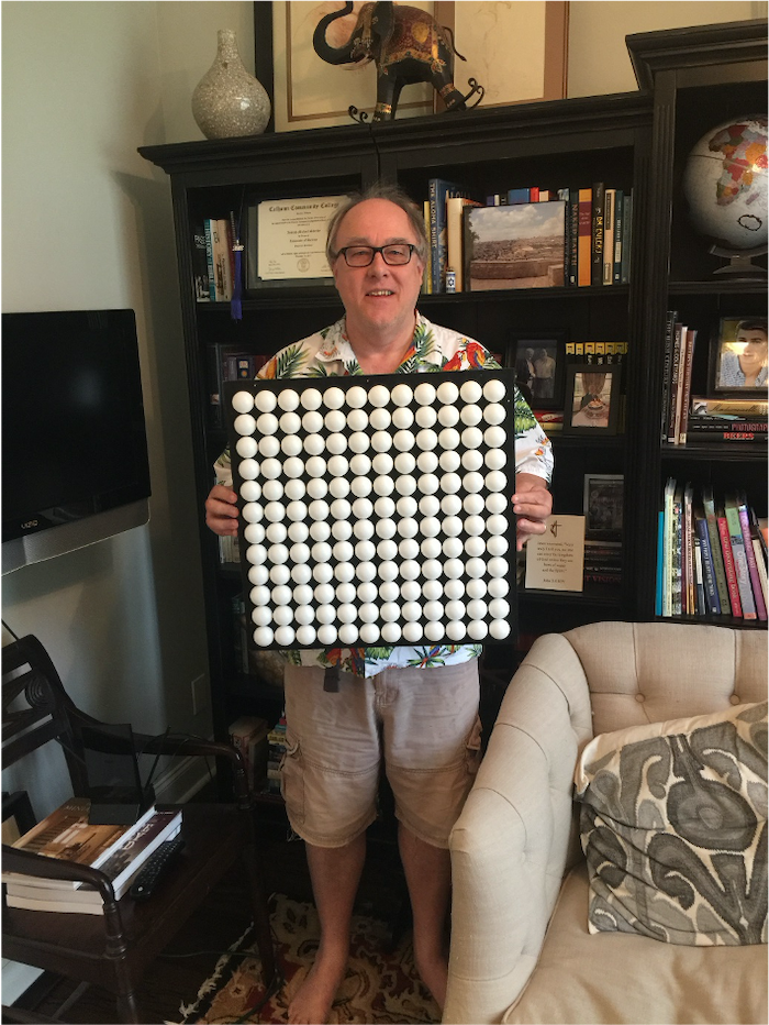
Eventually, I was the proud possessor of my very own 12 x 12 ping pong ball array. I flatter myself that it’s the best one in the neighborhood where I live (LOL).
|
Oh, the excitement of holding your first ping pong ball array. |
While I think about it, one thing I should note is that I’m driving this bodacious beauty using a Seeeduino XIAO microcontroller. Although it’s no bigger than a regular postage stamp, the Seeeduino XIAO boasts a 32-bit Arm Cortex-M0+ processor running at 48 MHz with 256 KB of flash memory and 32 KB of SRAM. Even better, it costs only $4.90 and it can be programmed using the Arduino integrated development environment (my cup runneth over).
I was happily programming my array when my chum, Ted Fried, who is an FPGA designer at Apple, suggested I hold a competition. Ted’s idea was that people could write programs to run on my array and email then them to me. I would then run the programs on my array, video them running, and post the results to YouTube. Eventually, we would all vote to determine which programs offer the coolest and/or most interesting and/or most spectacular effects.
There was just one small flaw with this cunning plan, which is that it would be almost impossible to create and debug such a program without having an array to run it on, which sort of defeated the point of the exercise.
To cut a long story short, we came up with an even more cunning idea, which was to use the Arduino’s Serial Monitor as a sort of simulator. The clever part here was implemented by my chums at Alorium Technology, who created a NeoPixel_Simulator library. This means you can write a program as if you were going to use Adafruit’s NeoPixel library, but instead of using the statement “#include ” to use the NeoPixel library, we use “#include ” to drive the simulator. The rest of the program stays “as-is,” which is Cool Beans whichever way you look at it.
The workings of the simulator, including where to obtain a free copy, are documented in excruciating detail in this column. For the moment, however, feast your eyes on this video showing a “Worm” programming running on the real array and on the simulator.
But wait, there’s more, because I just discovered that, as seen in this video the nefarious Bitluni first went on to create a 40 x 30 = 1200 ball array. More recently, as seen in this video, the overachieving Bitluni has created a 48 x 40 = 1920 ball array.
I can think of so many things I could do with a 1920 ball array. For example, can you imagine playing a game of Tetris on such a ping pong ball wall? Suppose you used artificial intelligence (AI) and machine vision to watch your hands and use these to control the game -- gestures made with your right hand could be used to move the falling pieces left or right, while your left hand could be used to rotate them as they fall.
On the one hand (no pun intended), I’m very happy with my 12 x 12 array, not least that it’s small enough that my wife (Gina the Gorgeous) doesn’t mind me having it in the house. However, I fear Gina would draw the line at my constructing a 48 x 40 array on the wall of our family room. Still and all, as they say, I fear I’m experiencing ping pong ball wall envy (and it’s not often you expect to hear yourself say that). How about you? Could you be tempted to build a ping pong ball array of your own?
Clive “Max” Maxfield received his B.Sc. in Control Engineering from Sheffield Hallam University in England in 1980. He began his career as a designer of central processing units (CPUs) for mainframe computers. Over the years, Max has designed all sorts of interesting “stuff” from silicon chips to circuit boards and brainwave amplifiers to Steampunk Prognostication Engines (don't ask). He has also been at the forefront of electronic design automation (EDA) for more than 30 years. Already a noted author of over a half-dozen books, Max is always thinking of his next project. He would particularly like to write for teens, introducing them to engineering and computers in a fun and exciting way. For this is what sets “Max” Maxfield apart: It is not just what he knows, but how he relates it to the learner.
About the Author(s)
You May Also Like


