The techniques discussed here go far beyond flashing LEDs.
October 1, 2022
Good grief! I simply cannot believe that we’re already at Part 7 of what was originally conceived as a trio, triad, or troika of articles. In my previous column, we wrote some simple Arduino sketches (programs) to perform experiments using one of Adafruit’s 8-Element tricolor NeoPixel Sticks.
Experiment #1 involved us lighting all of the pixels in the stick simultaneously. We started by lighting them all red, waiting a second, then lighting them all green, waiting a second, then lighting them all blue, waiting a second, and performing these actions over and over again.
In Experiment #2, as opposed to lighting all of the pixels simultaneously, we decided to light them one at a time without turning the previous pixel off and with a 100 millisecond (ms) delay between each pixel. Once again, we started by lighting them red, then green, then blue, then doing it all over again as illustrated below.

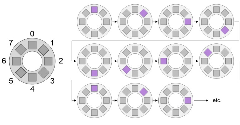
Just for giggles and grins, we closed our previous column with a thought experiment. We decided that we wanted to do next was to light the pixels one at a time as in Experiment #2. This time, however, whenever a new pixel lights up, we also want to turn the old pixel off. Just to mix things up a bit, we decided to use the magenta color for this experiment as illustrated below.

Your “homework,” as it were, was to cogitate and ruminate over the task of how we go about turning the old pixel off. There are multiple ways to do this. I can think of four “off the top of my head.” So, how many did you come up with?
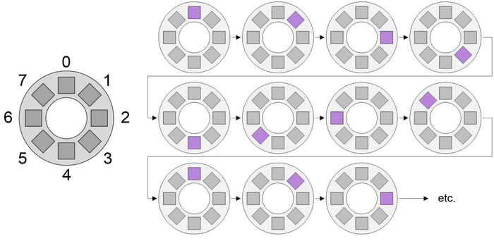
Before we plunge into the fray with gusto and abandon (and aplomb, of course), it might be worth noting that I personally find it easier to think about this sort of thing by visualizing our eight pixels as being arranged in a circle as illustrated below.
So, how are we going to turn the previous pixel off when we turn the new pixel on? Well, let’s start by doing it the wrong way, which will help us to wrap our minds around the underlying problem. From our previous experiments, we know that NUM_NEOS is a constant that’s been assigned a value of 8; also, that we’ve defined COLOR_MAGENTA and COLOR_BLACK as 24-bit hexadecimal values (8-bits each for the red, green, and blue color channels). Now consider the following snippet of code:
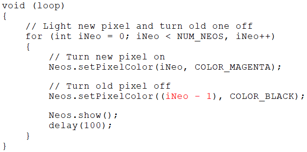
As we see, we’re using a for() loop to cycle through the pixels from 0 to 7, where the variable iNeo is used to point to the current pixel of interest. For each pixel position, we turn the new pixel pointed to by iNeo on, and we turn the old pixel pointed to by (iNeo – 1) off.
It’s always the end conditions (also known as “corner cases”) that cause us problems. In this case, the problem occurs when iNeo is pointing at pixel 0, because this means that (iNeo – 1) equals –1, which is not a valid value because our pixels are numbered from 0 to 7. What would happen if we ran this program? I’m afraid to find out (if you run it yourself, please let me know what happens).
Since the problem occurs only when iNeo is pointing at pixel 0, the obvious solution is to add a test to address this case as follows:
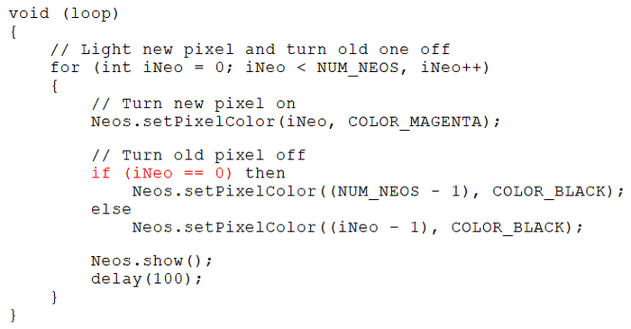
As we see, we’ve added a test to see if (iNeo == 0). If this is true, then we turn the pixel at (NUM_NEOS – 1), which is 8 – 1 = 7, off; otherwise, we go back to using (iNeo – 1) for the rest of the pixels. Note that the reason we use (NUM_NEOS – 1) instead of simply turning pixel number 7 off is to future-proof our code in case we one day decide to use a stick (or ring) containing more (or less) pixels.
Now, this is a perfectly serviceable solution, but it has to be acknowledged that it lacks a certain elegance. I personally dislike having to treat a single item differently from all the others. It would be nice to be able to present at least a hint of a sniff of a whiff of panache. (You probably think I should have shown this test colored in green because it works, but I’m leaving it colored red because I don’t like doing it.)
Happily, there are a number of ways we can go about this. The first requires that we understand the way in which computers store and manipulate numbers. Also, it only works when the number of pixels we are playing with is a power of 2, which is the case in this case, if you see what I mean, because we currently have 8 pixels and 8 = 2^3.
Earlier, we noted that when iNeo is pointing at pixel 0, this means that (iNeo – 1) equals –1, which is not a valid value because our pixels are numbered from 0 to 7. The thing is that the computer actually uses a value of all 1s to represent –1.
We don’t want to get into signed binary numbers here, but there’s another way to think about this, which is that an int (integer) like our iNeo variable is represented using a fixed number of bits (16 in the case of an Arduino Uno). Let’s assume that this variable already contained all 1s, in which case adding an additional 1 will cause it to overflow, ending up containing all 0s. Contrariwise, if the variable already contains all 0s, then subtracting 1 will cause it to underflow, ending up containing all 1s.
What we are going to do is to use the bitwise AND operator (‘&’) to logically AND the value resulting from the (iNeo – 1) operation with 0x7 (hexadecimal 7), which is 111 in binary (the compiler will automatically insert leading 0s as required). (If you are new to programming, then you may wish to check out my Masking and the C/C++ Bitwise Operators column, which provides a jolly good introduction to this topic.) The easiest way to visualize what we are doing here is with a table as illustrated below:
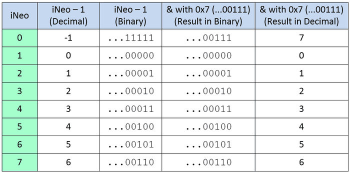
In the case of pixels 1 to 7 (001 to 111 in binary), subtracting 1 leaves 0 to 6 (000 to 110 in binary). Since these values all fit in the least-significant three bits, ANDing them with 0x7 (111 in binary) has no effect and leaves them “as-is.” However, in the case of pixel 0, subtracting 1 leaves us with 1111111111111111 (remember we’re assuming an Arduino Uno with 16-bit integers). ANDing this value with 0000000000000111 (remember the compiler adds leading zeros) leaves us with 111, which is 7 in decimal, which is what we want (I feel a “Tra-la!” is in order). This allows us to rewrite our code as shown below: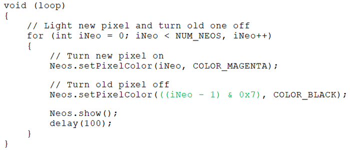
As we see, we no longer need to perform a test. Instead, we can use a single statement to turn any of our old pixels off.
The main problem with this approach is that—as we previously noted—it works only when the number of pixels is a power of 2. If we were to decide to use one of Adafruit’s 12-NeoPixel Rings, for example, then this masking technique would not work (sad face).
Fortunately, there’s another approach we can use (happy face). Return to look at the image showing the pixels arranged as a ring and visualize this as being drawn in chalk on the floor. Now suppose you are standing next to one of the pixels—let’s say pixel 4. There are two ways for you to get to pixel 3. One is to walk one pixel anticlockwise (we can think of this as representing –1); the other is to walk around the ring 7 pixels clockwise (we can think of this as representing (NUM_NEOS – 1)).
This is where we turn to another C/C++ operator called modulo (‘%’). In C and C++, if x and y are integers, the remainder from an integer division (x / y) is discarded. By comparison, the modulo operator (x % y) returns the remainder from the division. This leads us to the following table:
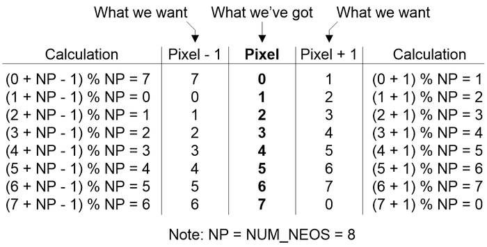
In this case, let’s start with the “What we’ve got” column shown in the center in bold. If we wish to determine the value of the previous pixel, then what we want is (pixel – 1), in which case the appropriate calculation is shown in the left-hand column. Alternatively, if we wish to determine the value of the next pixel, then what we want is (pixel + 1), in which case the appropriate calculation is shown in the right-hand column.
Let’s put this into practice as illustrated in the code snippet shown below:
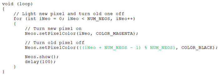
Once again, we no longer need to perform a test. And, once again, we can use a single statement to turn any of our old pixels off (in this case we are using the “Pixel – 1” calculation from our table to turn the old pixel off). Last, but certainly not least, let’s consider another way of doing things that gets rid of our for() loop as follows:
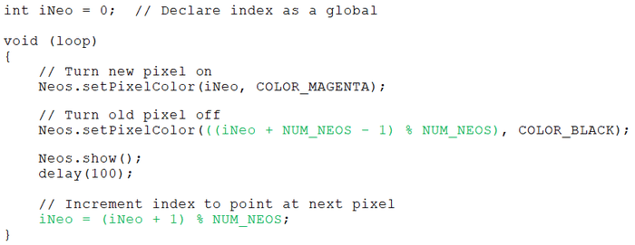
Personally, I find this approach makes things a little easier to wrap one’s brain around. What we are doing is declaring the pointer to our pixels, iNeo, as a global variable that we initialize to contain 0.
Once again, we are using the “Pixel – 1” calculation from our table to turn the old pixel off. Also, at the end of the loop, we use the “Pixel + 1” calculation from our table to point iNeo at the next pixel in the series.
Phew! I know there’s a lot to think about in this column if you are new to programming, but it’s really not too bad. The important thing to note is that the techniques we’ve discussed here (like using masks and the modulo operator) are applicable to a wide range of tasks that go far beyond flashing LEDs.
I think we’ll stop here for the moment to let all of this sink in. As always, I welcome your captivating comments, insightful questions, and shrewd suggestions regarding anything we’ve discussed in this column.
About the Author(s)
You May Also Like


