Three experiments and a captivating conundrum.
August 24, 2022
Hi there, and welcome to Part 6 of this increasingly misnamed (or miscounted) trilogy of columns. Just to make sure we’re all tap-dancing to the same skirl of the bagpipes (and I know whereof I speak, because my father was a tap-dancer on the variety hall stage prior to WWII, and he was in a Scottish Reconnaissance regiment during WWII), in Part 1, we ambled our way to the idea of light-emitting diodes (LEDs). In Part 2, we rambled through the concepts of forward voltage drop (VF), maximum forward current (IF), and current-limiting resistors.
In Part 3, we meandered through the notions of pulse-width modulation (PWM), and tricolor red, green, and blue (RGB) LEDs. In Part 4, we surprised ourselves by finally coming to meet and greet WS2812 tricolor LEDs (aka NeoPixels). And, most recently, in Part 5, we learned how to control our NeoPixels and we discovered how long it takes to upload 100 NeoPixels (spoiler alert; it’s 3 ms when using an Arduino Uno).
If you haven’t already done so, bounce back to Part 5 and remind yourself how to load Adafruit’s NeoPixel library, without which the effects we discuss in this column will be... well, nonexistent, really. Also, for the purpose of the following sketches (which is Arduino’s name for programs), we are going to be using one of Adafruit’s 8-Element NeoPixel Sticks.
![]()
Now, before we go any further, we’re going to need to define some colors to work with. In Part 3, we discussed how we could use red, green, and blue (RGB) light sources to act as additive primary colors. Also, we discussed how we could create a cornucopia of colors by varying the intensities of these primaries.
Assuming we have three primary colors (it’s possible to use more than three), we can obtain three secondary colors by mixing different combinations of our primaries: red + green = yellow, green + blue = cyan, and red + blue = magenta. It’s also possible to create six tertiary colors by reducing the intensity of one of the primaries.
One way to show the relationships between primary, secondary, and tertiary colors is in the form of a color wheel, which provides an abstract illustrative organization of color hues around a circle (don’t get me started on the definitions of shades, hues, tints, and tones).
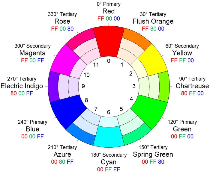
I must admit that I’m rather proud of this diagram, which contains a host of useful information, including the 8-bit RGB values in hexadecimal. When I’m playing with NeoPixels, one of the things I usually do early in the code is define all of these colors as follows (note that the line numbers have no meaning at this time beyond providing us with a point of reference).
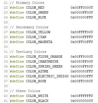
It’s useful to remember that #define statements are used by the C/C++ pre-processor and they don’t consume any space in the microcontroller’s memory once the code is compiled. This means that you can add these definitions into all your NeoPixel programs, even if you don’t plan on using all the colors in any particular program.
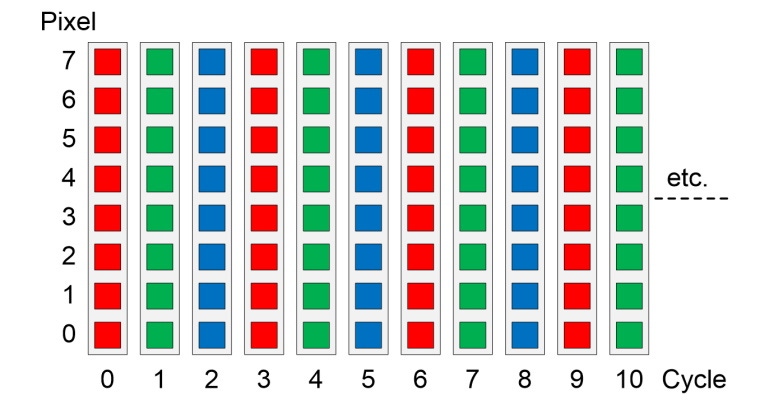
Let’s start by lighting all of the pixels simultaneously. Let’s assume that we have eight NeoPixels numbered from 0 to 7 on a strip as we discussed earlier. Let’s also assume that we want to light them all red, wait a second, then light them all green, wait a second, then light them all blue, wait a second, and then do it all over again as illustrated below.
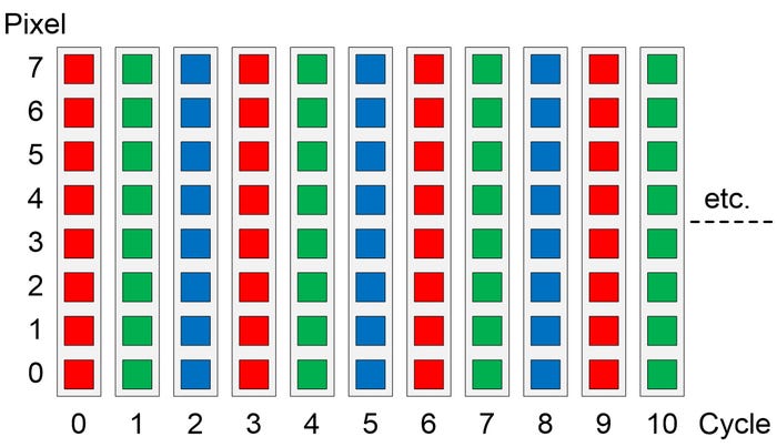
We discussed how to instantiate and initialize our string of NeoPixels in Part 5, so we won’t go over that again here. All we need to know at this time is that we’ve defined NUM_NEOS (the number of NeoPixels in our string) as being 8. Based on this, the contents of our Arduino loop() function could look as follows:
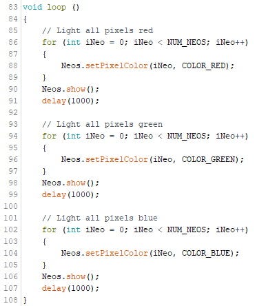
I mentioned some of the coding conventions I use in my previous column (4-space intents, ‘{‘ and ‘}’ vertically aligned, etc.). A couple of additional points are that I try to always use ‘{‘ and ‘}’ with a for() loop, even if it contains only a single statement (see Lines 87 and 89, for example). I do this because it makes things easier when I want to add debugging statements like Serial.print() later, not least because it helps prevent the adding of those statements from introducing additional bugs.
Also, I typically declare my control variables inside their associated for() statements (e.g., int iNeo = 0; in Lines 86, 94, and 102), thereby limiting their scope only to the for() loop itself. Furthermore, I tend to not use single letter variable names like ‘i’ and ‘j’ (or ‘x’ and ‘y’) for these control variables. Instead, I try to use variable names with three or more characters because this makes things easier to understand in the future.
Returning to this particular program; observe that the Neos.show() statements appear outside their associated for() loops. As we discussed in my previous column, Neos is the name we’ve given to our string of NeoPixels, and Neos.show() uploads all of the color values from the virtual NeoPixels in the microcontroller’s memory into the physical NeoPixels in the real world. Having the Neos.show() statements outside the for() loops is what makes all of the pixels change color at the same time.
Now suppose that, as opposed to lighting all of the pixels simultaneously, we decide that we wish to light the pixels one at a time without turning the previous pixel off and with a 100 ms delay between each pixel. We’ll start with red, then green, then blue, then do it all over again as illustrated below.
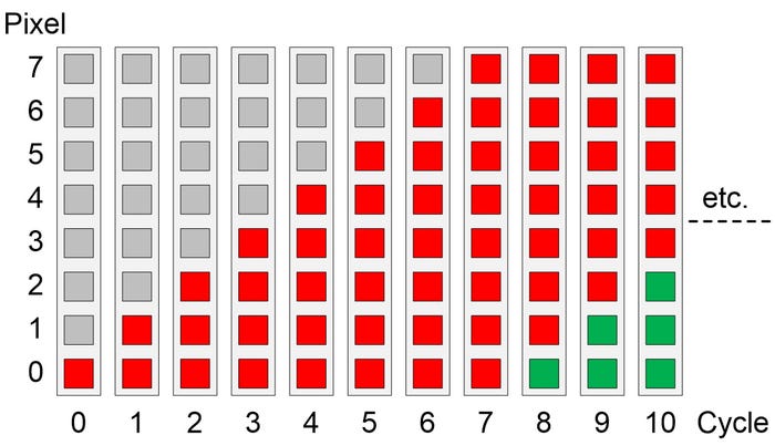
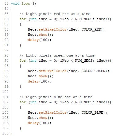
Achieving this requires only minimal changes to our original program as illustrated below. As we see, all we’ve done is move the Neos.show() and delay() statements inside their respective for() loops (Lines 89 and 90, for example), while also reducing the delay from 1000 ms (one second) to 100 ms (a tenth of a second).
Just for giggles and grins, let’s close with a thought experiment. What we want to do now is to light the pixels one at a time like before. This time, however, whenever we light a new pixel, we want to turn the old pixel off. Just to mix things up a bit, let’s use the magenta color for this experiment as illustrated below.
![]()
Your mission, should you decide to accept it, is to cogitate and ruminate over the task of how we go about turning the old pixel off. At least four different techniques spring to my mind—can you guess which ones I’m thinking of? All will be revealed in my next column. Until then, as always, I welcome your comments, questions, and suggestions.
About the Author(s)
You May Also Like


