Achieving Enlightenment With Virtual Design
June 18, 2014

Let's face it, we live in a profit-driven world. At an average cost of $8,929 per spin, making sure the first prototype is also the last is absolutely on your list of KPIs. At the same time, you've also got tight schedules to meet. That's why you have different designers working on different aspects of the design, in parallel, trying to get it done faster. Virtually assembling your product, assembling the PCB in the mechanical enclosure, and checking for any clearance violations through automated design rule checks are more accurate methods and will reduce the need for printing and cutting paper models, saving you time and money. Yet studies by the Aberdeen Group have shown that managing ECAD/MCAD data integrity issues consumes 26% of an engineer's time.
Version control can help
One pain point when managing your ECAD and MCAD design data is keeping both sides of your design in sync, ensuring that your PCB designers are working with the latest mechanical models, and vice versa.
A formal automated version control system, such as free open- source solutions like Subversion, linked with your design environment and implemented as part of your workflow, provides two major benefits. First, and most obviously, you can always confirm that you are working with the latest version of a file. When properly integrated, your design tool will tell you proactively when you are out of sync with a repository. Second, all changes are automatically logged and tracked with changes made, date and timestamps, who made the changes, and then optionally a comment.
This way your designers can be sure they are working with the latest files and all documentation is complete.

Better 3D models
Virtual design, or virtual prototyping as we call it in the electronics world, allows you to simulate and test your entire design in a virtual environment so you can be confident your design will work when you make your physical prototype. Using detailed STEP models for components and enclosures, instead of just an outline, provides greater accuracy.
Unlike ECAD, the MCAD world has embraced more open standards. All the major players in the industry -- be it Dassault SolidWorks, Autodesk Inventor, or Siemens Solid Edge -- support the most common ones for importing 3D models, STEP, and IDF. This makes it easier for ECAD tools to import MCAD data. With these highly accurate and easily readable 3D models coming from the MCAD tools, it is now possible to automatically define the exact board shape and size that will fit in the enclosure, which can further increase your productivity.
In order to reduce the need for paper models further, your design tools will need to support all the technologies you plan on utilizing in your design. In today's world where space is limited, that often means rigid-flex. Beyond reducing the size of the board allowing you to fit your product in a smaller enclosure, utilizing rigid-flex circuits reduces the need for interconnect wires and soldering of connections, which brings down the manufacturing cost in high yield runs.
Better 3D integration
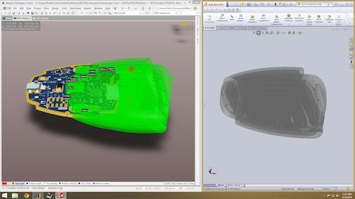
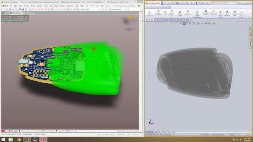
Even still, importing and exporting is error-prone and time consuming. Your tools need to work seamlessly together with changes in any given domain, automatically verifying with the others. Recently, Native 3D PCB design has become a possibility. In a Native 3D PCB workflow, ECAD and MCAD tools are linked bi-directionally in real- time so that changes made to the enclosure are instantly reflected on the ECAD side, thus eliminating the need to import and export huge STEP files. By eliminating the need for importing and exporting, modern design tools have the ability to increase productivity further and reduce errors beyond that which can be accomplished with STEP models and version control alone.
A fully integrated workflow
Looking across the entire design process, importing and exporting is never ideal. The kinds of productivity gains we are seeing in modern tools with Native 3D PCB support should also be demanded across the entire design workflow. With modern tools, replacing a FPGA device is as easy as replacing it in the schematic, placing it on the PCB, performing an automated PIN swap to reroute it, and pushing the results back to the FPGA design.
To take full advantage of the capabilities of virtual design, your tools must support all of the above in a way that doesn't hinder your productivity. Now that you're saving time without creating problems, and confident your design will function, you can focus your efforts where your value as a designer and leader can really shine -- product differentiation and product viability.
— Darin ten Bruggencate works in product marketing for Altium Inc.
Related posts:
About the Author(s)
You May Also Like


