Specifying and Qualifying Sensors for Robot Navigation
To achieve optimal accuracy in robot navigation, you have to choose the right sensors.
January 30, 2022

Charles Pao, CEVA
For robot navigation applications, it’s important to have accurate data on position and heading, provided by multiple sensors. If your robot doesn’t know where it is, or which way it’s pointing, it’s going to be difficult to go to where you want it. In addition to accuracy, designers should also consider factors such as cost, power consumption, integration effort, and device size to ensure they pick the optimum component for their requirements.
Errors Assemble
When a robot is moving autonomously, the errors from its positional sensors will compound over time. For example, for an autonomous robotic vacuum cleaner, any measurement of the direction it’s pointing will inevitably become inaccurate. The further the robot moves away from a known position, the greater the error in position data is accumulated by this directional error.
To achieve the most accurate results, it’s often best to use multiple sensors of different types and to combine their different data streams. For the vacuum cleaner, we could use wheel encoders to measure how far the robot has moved, as well as optical flow sensors to provide additional motion information for comparison and calibration. Then, an inertial measurement unit (IMU) can independently provide data on orientation, lateral acceleration, and angular velocity.
By putting it all together, the right software can determine the robot’s position and which direction it’s moving in, as well as providing suitable information on the likely errors in this data.
Just the Facts
We know that accuracy is important, and that errors will compound, but how should we go about choosing the right sensors for our robot navigation application?
Like most design issues, it’s often best to work backward from the desired result. The design specification for our robot should define what level of accuracy is required, and what kind of errors are acceptable. Armed with this information, we can then work out what performance we need from each sensor, and what tolerances we can handle without compromising the overall design.
In theory, we could do this by reading datasheets and comparing the various minimum and maximum errors quoted. We could then combine these numbers to derive overall error figures for our robot vacuum cleaner.
This is the most common approach, but we can do better.
Characterizing in Detail
To make the best design choices, we need to have a comprehensive view of each sensor’s characteristics, and to map out errors, and their expected impact.
The best way to account for these sensor attributes is to study them with data and to characterize how their behavior changes in all possible circumstances. Ideally, we would have a comprehensive data collection, comprised of measurements for every single possible permutation of key metrics, including orientation, operating mode, and temperature.
This automated data collection system would require suitable equipment. The permutations are probably the most difficult part of this system to set up. Single-axis rotations can be stepped through with a precision gimbal. Then, putting that single-axis gimbal perpendicular to another allows full tri-axis motion.
Custom PCBs can be designed to communicate with the sensors, change operating modes, and collect data. Creating enough boards to reach a statistically significant number of sensors tested ensures that we can get adequate data to fully characterize the typical sensor.
Next, we can put these boards and gimbals in a temperature-controlled chamber, and modify their temperature at the same time as the gimbals step through various positions and the sensors their operating modes. Furthering sensor study, a heat and humidity chamber can artificially age these boards, and a Helmholtz coil can be used to measure the effects of changing magnetic fields. Add in a computer to run these systems, log the data, and the software to analyze it, and we have a full sensor characterization system.
Detailed Insights from Test Data
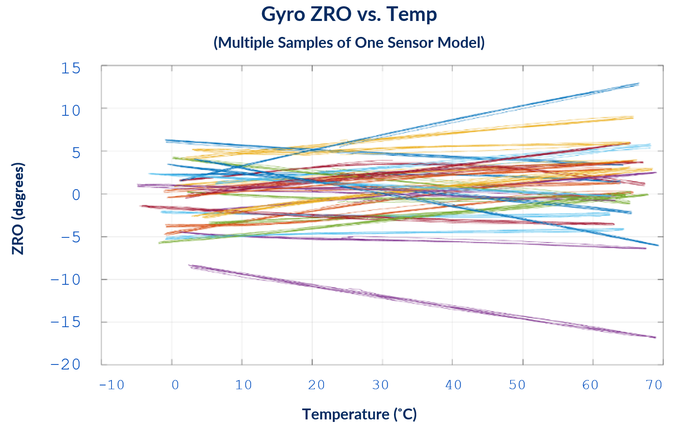
While this system is complex to set up, the results provide insights that are well beyond what any datasheet can give us. For example, see Figure 1, which shows the relationship between gyroscope bias, or zero rate offset (ZRO), for multiple sensors tested. ZRO is the angle that a sensor reports when it is at rest, and should ideally read zero degrees.

Each line in Figure 1 shows the effect of changing temperature on ZRO for a single sensor – all of the sensors are the same product model. Each sensor behaves differently as temperature changes. Some are strongly positive, others negative, some are less influenced by temperature, but all of them have different ranges of effect.
The same level of detailed data collection can be done with the other parameters (such as offset, gain, skew, rotation, noise, non-linearity) with varying conditions of temperature, voltage, aging, and operation mode.
For any given application, some factors will be more important than others. For example, if our robot vacuum cleaner is expected to operate in a domestic household, the range of operating temperatures is likely to be low – most people keep their houses within a few degrees of a typical figure. Alternatively, a lawnmower robot operating outside might be expected to perform accurately over a much wider temperature range dependent on the weather conditions.
Some of these effects can be modeled and compensated in our design, and some reflect limitations that dictate the performance limits of the system. We must carefully weigh sensor characteristics against external factors such as cost and integration effort, to make the best selection of sensors for the robot application. With comprehensive sensor characterization, we go far beyond what’s provided in the datasheet and can ensure we have enough information to make the right design decisions.
Robotic systems are a complex beast, requiring the right mix of carefully picked mechanical, electrical, and programmed parts. There are so many combinations of places where choices need to be made and things can go wrong. CEVA’s ‘Navigating the Complexities of Robotic Mapping White Paper’ aims to guide users in getting the best sensors, making the right test plan, collecting data, and finding insight in the analysis, so that a suitable sensor system can be designed for your robot. Here’s the whitepaper.
Charles Pao is Hillcrest’s first point of contact for information and support. He has held various account and project management roles. Pao has earned Bachelor of Science degrees in electrical engineering and computer engineering from Johns Hopkins University.
You May Also Like


