Benefits of Direct Charging Design in Wireless Power
March 8, 2013

Wireless power transfer is defined as a transmission of electrical energy from a primary (Tx) to a secondary side (Rx). The two sides take advantage of mutually coupled coils. This power transfer relies on magnetic induction between the primary and secondary coils. The two coils simply form two halves of a transformer and can be modeled as a loosely coupled transformer.
The primary side has a flat surface that allows the secondary coil to be placed on top of it. When a Tx and Rx are aligned and placed near one another, they form a mutually coupled-inductor relationship, or a simple transformer with air core. Appropriate shielding between the bottom side of the Tx coil and top side of the Rx coil is required. The shielding material on both sides serves as a magnetic flux short. This allows the magnetic field lines (flux) to be contained between the two coils and allows efficient power transfer. The direction of power is always going into the receiver that typically consists of portable devices.
Wireless power DC/DC system efficiency
As we just described, a wireless power system consists mainly of a primary and secondary side coupled with coils. System efficiency is defined as the ratio of final power transferred to the load with the DC input power applied to the transmitter (Equation 1):
Efficiency (%) = (DC Output Power) / (DC Input Power)


Figure 1 shows a schematic diagram of a wireless power transfer system, consisting of a wireless power transmitter coupled to a wireless power receiver.
Improving system efficiency requires reducing losses within the path from the input to output. This depends on how the specifics of the transmitter module (primary coil, AC/DC converter, driver), and the receiver (rectifier, voltage conditioner, secondary coil, battery charger), are combined and aligned during power transfer. Since the two modules are two separates pieces, the efficiency of each module is independent from the other. The focus of this blog is the Rx side.
Improving system efficiency requires reducing the losses within the path from the input to the output. This depends on the combination of specifics of the transmitter module (primary coil, AC/DC converter, driver), and the receiver (rectifier, voltage conditioner, secondary coil, battery charger), and their alignment during power transfer. The focus of our discussion in this article is on the receiver side. Detailed information about the receiver sub-circuitry is provided next.
Wireless power receiver
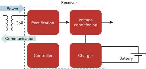
A wireless Rx typically is part of a portable device, such as a cellphone. The Rx itself consists of multiple key circuits as shown in figure 2. The secondary coil is responsible for receiving the transferred power from the transmitter as magnetic flux. The rectification circuit is used to convert the received AC-to-DC power. A voltage conditioning circuit buffers the unregulated received DC power to a regulated and clean DC output power ready for down system use. The communication circuit is responsible for all communications with the transmitter and unidirectional from receiver to the transmitter.
About the Author(s)
You May Also Like


