Complete CNC Board Implementation
November 20, 2012

Computer numeric control (CNC) is a computer-based system used to control tools such as milling machines, lathes, routers, lasers, punches, water jets, and 3D printers. For a long time, CNC equipment remained constrained to the industrial shop. With the recent proliferation of personal computers, however, CNC has managed to move into the home environment with an ever-increasing number of do-it-yourself (DIY) enthusiasts and hobbyists building their own CNC equipment. The reason this technology enjoys such a large acceptance is because it has the accuracy and repeatability that only a computer-controlled system can offer. In this article, I detail an implementation for a set of electronics that can be used to control pretty much any small or midsized CNC machine.

The CNC motherboard
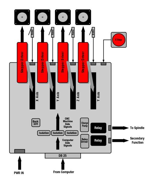
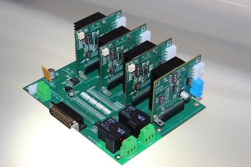
I call this implementation the CNC motherboard, as it revolves around a backplane that accepts motor driver modules to drive the CNC machine axes. In this incarnation, the CNC motherboard can support up to four axes, which is more than enough for the great majority of CNC equipment topologies being built today. The motor driver modules typically are based on bipolar stepper motor drivers with a step/direction interface. In essence, any motor topology can be used, as long as it works by moving according to STEP commands. Since the number of stepper motor power stages with an inherent step/direction interface is always growing, we see the stepper motor ruling the great majority of DIY CNC equipment implementations.
The control of these four axes is supported by a series of blocks. The brain of a CNC machine is a computer called the CNC controller. It is in charge of sending a series of STEP pulses and setting the ENABLE and DIR control lines to the motor driver modules according to a command better known as G code. A G code command can be anything like "move in a line to coordinates X,Y,Z at speed F," "move in a curve," "drill a hole," and so forth. The CNC controller interprets this command and generates the respective combination of STEP/DIR pulses, and at the right frequency, to achieve the required motion.
The CNC controller for our DIY CNC machine can be any personal computer (PC) with a parallel port. Although PCs are no longer being fabricated with parallel ports, adding this resource in the form of an expansion card is very simple. The PC connects to the CNC motherboard through this parallel port, granting us a total of 12 output functions and five inputs.
Before we start distributing the control signals in and out of the different control functions, we add an isolation block for two main reasons. First, this isolation stage protects the computer in case something goes very wrong. Since the motor drivers can be employing high voltages that can hurt the computer, it is best to make sure the computer side cannot come in contact with this higher form of energy. Second, the isolation helps to decrease the control line's noise caused by ground bouncing.
The control of four motor modules claims nine control signals: one ENABLE, which will be shared among the four modules; one STEP; and one DIR per module. The remaining outputs are distributed as follows. Two are used to control two 250V AC/30A relays. The other output runs a watchdog protection block, often referred to as the charge pump.
About the Author(s)
You May Also Like


