How to Build a Better Buck Converter for Power Conversion Circuits
Power conversion design is needed for most battery systems. But it doesn’t all have to be done on a test bench.
May 24, 2021

Another lifetime ago, and as a young engineer, I had to design a power conversion system. The input power came as raw electrical energy from a jet engine during flight. The output power was input to sensitive electronics and instrumentation systems on the aircraft.
The first stage of the power conversion process was to clean up the raw, very spikey current and voltage flying off the jet turbines. This required a collection of hefty capacitors for voltage and inductors for current spikes.
The next stage of conversion was a bit more sophisticated, requiring all kinds of converters, from analog to digital (AC/DC), digital to digital (DC/DC), buck converters, up and down converters, and lots of grounding protection capacitors.
I was later to learn the most often used type of conversion is the DC-to-DC one. There are many power electronic circuits used to convert from one DC voltage to another. Probably the most widely used is the simple "buck" (or step-down) converter. A buck transforms a higher voltage (and lower current) input into a lower voltage (and proportionally higher current) output.
A buck converter is a class of switched-mode power supply (SMPS) devices that are typically containing at least two semiconductors, like a diode and a transistor. Modern buck converters frequently replace the diode with a second transistor used for synchronous rectification). Also, there is at least one energy storage element, a capacitor, inductor, or the two in combination.
Filters based on capacitors, sometimes in combination with inductors (e.g., RCLs), are included in the converter’s output (load-side) and input (supply-side) circuits to reduce voltage ripples.
Switching converters like buck devices provide much greater power efficiency as DC-to-DC converters than linear regulators, which are simpler circuits that lower voltages by dissipating power as heat without stepping up the output current.
Buck converters can be highly efficient and thus very useful for tasks such as converting a computer's supply voltage (often 12 V) down to lower voltages needed by USB, DRAM, and the CPU (5V, 3.3V, or 1.8V). The Texas Instruments video below provides a good review of buck converter design with component systems.
Designing with Buck Converters
Designing and modeling buck converters may appear simple in theory but can often be a difficult and time-consuming task.
Rather than jump to a physical test bench to prototype your next buck converter design, try using a cloud-based virtual workbench to model the circuit. You’ll be able to design, simulate, review results and adjust until satisfied – and all simulated on the cloud.
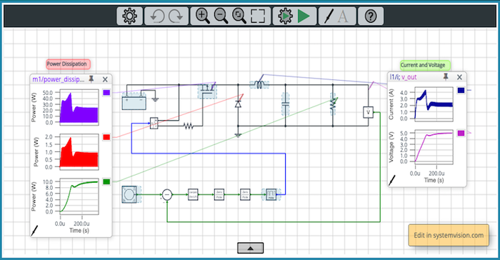
Here’s one example where a simulation is used to illustrate potential transients in a buck circuit design. The circuit uses power stage component selections. The results of the simulation – using Mentor-Siemens SystemsVision - closely match not only the expected voltages and currents but also the calculated component power dissipation levels. Efficiency is a key performance indicator for all modern power electronics.
This design includes a controller composed of ideal non-physical blocks representing the compensation function, the pulse-width modulation (PWM) generator, and a MOSFET gate driver. These math-based control elements allow designers to verify the circuit's closed-loop performance before designing the actual implementation circuits.
The advantage of cloud-based, interactive design is that the designer can change the key parameters and immediately observe the results. For example, the load resistance value can be tweaked, which changes the output load current. Or the output filter L and C values can be modified, as well as their parasitic resistances. The battery supply voltage, as well as the PWM frequency, can also be adjusted.
By changing these parameters and running new simulations, the designer gains a better understanding of their impact on the circuit's start-up performance and steady-state efficiency.

John Blyler is a Design News senior editor, covering the electronics and advanced manufacturing spaces. With a BS in Engineering Physics and an MS in Electrical Engineering, he has years of hardware-software-network systems experience as an editor and engineer within the advanced manufacturing, IoT and semiconductor industries. John has co-authored books related to system engineering and electronics for IEEE, Wiley, and Elsevier.
About the Author(s)
You May Also Like


.jpg?width=300&auto=webp&quality=80&disable=upscale)


