Creating an Animatronic Robot Head (Part 1)
Once you’ve created a fully articulated robot head, the next step is controlling it.
January 26, 2022

In my previous column, I described how my chum Steve Manley, who is based in the UK, and your humble narrator (I pride myself on my humility), who is based in the USA, decided to build some small (80 x 80 mm) circuit boards that we modestly monikered Steve and Max’s Awesome Displays (SMADs).
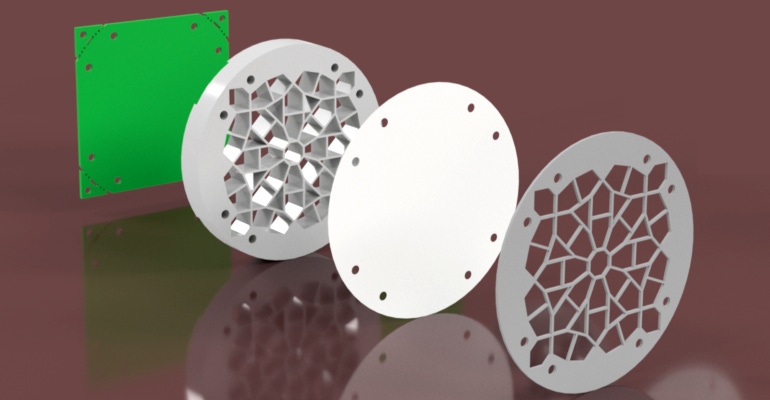
These little rascals each boast 45 tricolor LEDs of the WS2812 variety (commonly known under Adafruit’s NeoPixel nomenclature). What makes SMADs really stand proud in the crowd is the fact that we’ve augmented them with 3D printed shells and faceplates (a.k.a. facias). You can see these in the featured image accompanying this column.
The shells, which are used to compartmentalize the light from the LEDs, are 10 mm thick which helps prevent the light from looking like it’s coming from point sources. There’s also a thin diffuser layer mounted between the shell and the facia. For this, we used pieces of the white plastic separator sheets you can purchase for use with ring binders.
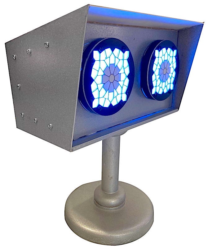
As I mentioned in the aforementioned column, one of the things I decided to do with my SMADs was to use them to form the eyes of a simple pseudo robot head. The reason I use the “pseudo” qualifier is that this is a robot in name only.
The base and the supporting column are made of wood I turned on a lathe and spray-painted to look like metal, while the main head is a mix of spray-painted wood and colored card (the machine screws are just for show because everything was joined together with my trusty hot glue gun).

I must admit that I was rather pleased with the way this turned out. I would have been quite happy experimenting with different color combinations and effects with my SMAD eyes. But then a friend said things would be more interesting if I were to add some motion into the mix.
The original suggestion was for each of the eyes to be able to pan (swing from side to side) and tilt (lean forward and backward) on an individual basis. Of course, it didn’t take long before this concept was extended to the entire head.
You know what it’s like. If you don’t have an idea in your head (which is my usual mode of being) you can be quite happy, but it’s hard to stop thinking once you do have an idea rattling around in there. In my case, it wasn’t long before I was channeling the boy in The Sixth Sense movie (“I see servos everywhere”).
|
I discussed all of this with my co-conspirator Steve, at which point we decided to set off on slightly different paths. I determined to start playing with some prefabricated pan-and-tilt servo assemblies, while Steve turned to his trusty 3D CAD modeling tool -- he’s grown to be a guru in the use of Fusion 360 from Autodesk -- and started to experiment in the virtual world.
I will regale you with the super-spiffy servo-related solutions associated with all of this in a future column. For the moment, let’s focus on the topic of control. In the longer term, I want to equip my head (by which I mean my animatronic robot head, not my poor old noggin, of course) with a selection of sophisticated sensors. For example, I’m thinking of a motion sensor so that the head and its SMAD eyes can turn to track people as they move around the room, a facial recognition sensor that can detect emotive expressions and respond (by changing the color of the SMADs) to happy, sad, or angry faces, and an audio sense capability that can cause the head to react to sounds.
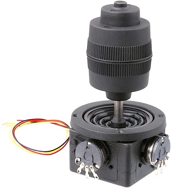
But all that’s for the future. In the shorter term, I want to have a couple of joysticks that I can use to control my head by hand (if you see what I mean). Steve had the same idea. Eventually, we both opted for the same JH-D400X-R4 devices, which are billed as 4-axis products (I found mine on eBay for around $16 apiece).
In reality, the 4-axis moniker is a bit of a misnomer, because these joysticks boast only three 10 kΩ potentiometers (pots). One responds to a forward-backward motion, another to a left-right motion, and a third (hidden inside) to an anticlockwise-clockwise rotary motion. The “fourth axis” of control is a pushbutton switch mounted on the top of the joystick.
These are perfect for what we want them to do, and I, for one, think they are a bargain at the price. In my case, I’m using a Teensy 3.6 microcontroller. This little beauty boasts a 32-bit 180 MHz Arm Cortex-M4F processor with 58 input/output (I/O) pins (25 of which can act as analog inputs if required), 1 MB of Flash memory, and 256 KB of RAM. This means that I have more than enough analog input pins available to feed the signals from all six of my pots directly into the MCU.
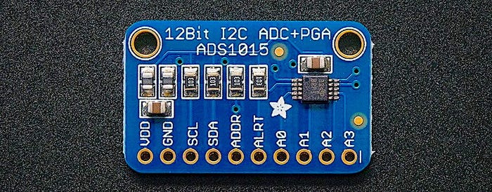
By comparison, Steve favors a low-cost Teensy LC for many of his projects. The LC features a 32-bit Arm Cortex-M0+ processor running at 48 MHz with 62 KB of Flash memory and 8 KB RAM. More importantly, the LC has only 27 I/O pins available, and Steve is using a lot of these for other things. As a result, he opted to feed the signals from his pots into two ADS1015 4-channel, 12-bit analog-to-digital converter (ADC) breakout boards (BOBs) from Adafruit. These communicate with Steve’s Teensy LC via a 2-wire I2C bus, which they share with a servo motor control board.

I’ll be talking about all of this in more (some may say excruciating) detail in a future column. In the meantime, I’d love to hear what you think about how things are going thus far.
About the Author(s)
You May Also Like


