Ode to Bodacious Breadboards, Part 2
There’s always something new to learn, even with something simple like breadboards.
April 15, 2024
At a Glance
- Multi-colored, self-adhesive 3-mm whiteboard graphic chart tapes can be used to indicate multiple power and ground rails.
- As opposed to terminating the ends of single-core breadboard wires with 90° flat cuts, it’s best to employ 45° bevel cuts.
I tell you, there’s always something new to learn, even when you are one of the world’s leading authorities on all things of an electronic nature (well, that’s what my mom thinks, and I certainly don’t wish to disillusion her). For example, I was just chatting with my friend Joe Farr in the UK, and he shared some very useful tips and tricks I’ll be using on my own breadboard-based prototypes and projects in the future.
In Part 1 of this mini-series, we introduced the concept of solderless breadboards, including their internal construction. One of the things we considered was the fact that some of these boards have split power and ground rails. These split rails can be incredibly useful if (a) you know they are there and (b) you are creating a prototype that employs multiple voltages, like 3.3 V and 5.0 V, for example.
Contrariwise, split rails can be a pain in the nether regions if you aren’t aware of their existence (some boards lack the breaks in the red and blue graphical lines that would give you a clue) and you neglect to add jumpers to link the two halves of the rails. I once spent much longer than I should scratching my head in puzzlement whilst trying to debug a circuit before I eventually realized that only half of my breadboard was powered up.
Another thing we discussed in Part 1 is the fact that different boards can have different numbering schemes. Some have their columns numbered from 1 to 63 (see [a] in the illustration below), while others are numbered from –1, through 0, to 61 (see [b] in the illustration below).
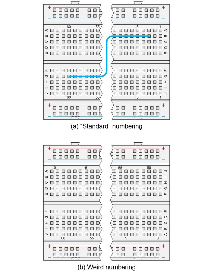
Standard versus weird-and-wonderful breadboard annotations. CLIVE "MAX" MAXFIELD
It’s the latter of these little scamps you need to watch out for. First, because the annotation for column 0 usually appears between two columns, which means you are obliged to count back from column 5 to determine which column actually is 0. Second, because column 1 on the top ends up being called column 60 on the bottom, while row A on the left ends up with the J annotation on the right, all of which makes it impossible to convey instructions like “Connect a wire between B3 and G60” because there are two B3s and two G60s.
Sometimes you run across breadboards that don’t have the red and blue power and ground lines drawn on them at all. For example, Joe ran across some very good full size breadboards costing only half the usual amount. In this case, the fact they were unmarked was an advantage because Joe does a lot of work with mixed-signal (analog and digital) designs that require +12 V, 0 V, and – 12 V for the analog, and +5 V and 0 V for the digital.
This is where we arrive at the first of Joe’s suggestions. In this case, he uses 3-mm-wide self-adhesive tape to boldly indicate which rail is which. He says you can get 20 rolls in 10 colors from Amazon.
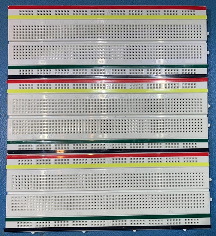
Using self-adhesive tape to mark different power and ground rails. JOE FARR
Different people approach breadboarding in different ways for different projects. Sometimes you just want to use a “quick and dirty suck it and see” approach to hook up a bunch of components to verify that something will work as planned, as illustrated below.
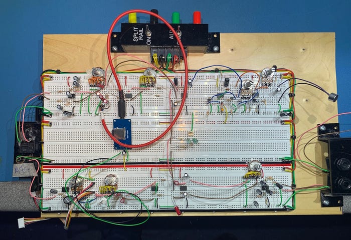
A “quick and dirty suck-it-and-see” breadboarding approach. JOE FARR
Some people prefer to use prefabricated multi-core jumper wires with male-male connectors when breadboarding. I often go this route myself.
Joe prefers to use single-core wire for his creations. He has rolls on the wall of his workshop and he simply cuts them to length as required, but kits of pre-cut single-core wires with stripped ends are available.
This leads us to another of Joe’s suggestions. He says that, as opposed to terminating the ends of single-core breadboard wires with 90° flat cuts (see [a] below), it’s best to terminate them with 45° bevel cuts (see [b] below). Joe says that forcing a flat cut end into a hole in the breadboard can occasionally cause damage to the grippers inside. Also, that a bevel cut end slides in a lot easier.

Alternative ways of terminating single-core wires. CLIVE "MAX" MAXFIELD
This makes perfect sense. I can’t think why I never thought of this myself before. I just checked one of the kits of pre-cut single-core wires I have lying around. The ends are all cut at 90°. They won’t be the next time I use them.
Returning to individual styles, some people prefer to take more time and make their breadboard-based projects look super spiffy. The image below reflects the early stages of one of my own projects from around 20 years ago (when I had a lot less sense and a lot more more time on my hands).
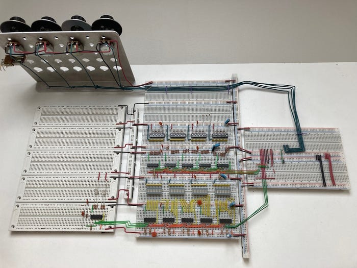
A more measured (and more time-consuming) breadboarding approach. CLIVE "MAX" MAXFIELD
As it happens, I never actually finished this project because I came up with a different way of doing things, but it now serves as a form of wall art in my office. It’s also a talking point (at least, I never stop talking about it).
By some strange quirk of fate, although this isn’t exactly breadboard-related, while I was writing this column, totally unprompted and out of the blue, another friend just emailed me with a link to a video snippet on YouTube showing I’m not alone when it comes to spending perhaps more time than is warranted on a simple task.
I have several more of Joe’s tricks to share, but I don’t want to spoil the excitement, so we’ll save those for next time. In the meantime, look at the image below. This is a project I’m currently working on. In particular, observe the two groups of eight 150Ω resistors.
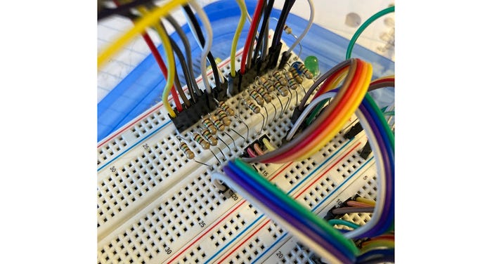
Two groups of eight resistors. CLIVE "MAX" MAXFIELD
I have two questions. First, can you envisage any potential problems that might arise from doing things this way? Second, can you think of a cheap and cheerful solution that will make things neater and less prone to failure, while also offering the opportunity to speed up future prototyping projects?
Until next time, I welcome your insightful comments, penetrating questions, and sagacious suggestions. Also, if you have any breadboarding tips and tricks you’d care to share, please feel free to email me at [email protected].
About the Author(s)
You May Also Like


