

Sign up for the Design News Daily newsletter.
How to Pick and Program a PIC, Part 1
Once you start using PICs, it’s hard to stop.
Clive 'Max' Maxfield
January 8, 2024
8 Min Read
JOE FARR
A lot of people disparage PIC microcontrollers but—as I now know to my cost—these little rascals have an addictive quality about them. They can make life incredibly easy with respect to prototyping projects and producing products, assuming you know what you are doing, and therein lies the tale…
I cut my programming teeth writing assembly language on 8-bit microprocessors circa the late 1970s. We’re talking about devices like the Z80 from Zilog and the 6502 from MOS Technology. Now, I’m not saying that these processors didn’t have their quirks, but I don’t recall anything that set my brain gyrating on its gimbals.
Over the past decade or so, I’ve spent a lot of time playing with 8-bit microcontrollers like the Arduino Uno R3, which is based on the well-known ATmega328P processor. This processor was originally created by Atmel, which was acquired by Microchip in 2016. Unlike microprocessors, which require external devices like memories to function, microcontrollers include memory (SRAM, Flash, and EEPROM) on the same chip as the processor, along with other functions like analog-to-digital converters (ADCs), pulse-width modulators (PWMs), and counter/timers. Happily, we can use the Arduino’s Integrated Development Environment (IDE) to capture our programs in C/C++, so no assembly language there.
This next part is a bit scary, so you may want to cover your eyes. A couple of years ago as I pen these words, I found myself in a bit of a pickle. I’d foolishly agreed to take over the maintenance of a company’s code targeted at 8-bit PIC microcontrollers from Microchip. I was aware that this code was in assembly language. However, having worked with several such languages in the past—even creating a couple of my own during my career—I fear I’d grown a little blasé and complacent. As a result, I overestimated my abilities while underestimating my tolerance for pain; that is, pain as it pertains to programming in PIC assembly language.
When I came to actually look at the code in question, my eyes started to water and shivers ran up and down my spine. I’d been told that the source code was heavily commented. It was. Unfortunately, the comments hadn’t been updated to reflect any changes made in the code over the years, leaving the two entities almost totally unrelated.
Even worse, when I looked at the code itself, I understood it as well as if it had been written in Egyptian Hieroglyphics. I downloaded and printed a manual for one of the PICs. It was 300 pages!
One of the problems is that the processors with which I am familiar are based on a Von Neumann architecture in which the memory contains both data and instructions. By comparison, the 8-bit PICs with which I was dealing are based on a Harvard architecture, which involves separate memory and signal pathways for data and instructions. Also, although this isn’t particularly relevant to what we are talking about here, PICs are Reduced Instruction Set Computer (RISC) machines, as opposed to the Complex Instruction Set Computer (CISC) machines with which I am more familiar.
Another issue is that the memory in PICs isn’t presented as a single contiguous whole. Instead, it’s split into small “banks” that are 128 bytes in size. This means that different variables end up being stored in different banks and—if you are writing in assembly language—you are obliged to keep track of things and switch back and forth between banks as required to access your variables. It gets worse. If you were thinking about creating an array of some data type where that array crosses from one memory bank to another, then my advice is to think about doing something else, like training squirrels, which would be much less wearing on the nerves.
And one more consideration is that PICs contain an inordinate number of Control and Status Registers (CSRs)—many of which may really be realized in memory—whose bits you typically must tweak to realize whatever effect you are hoping to achieve. On the one hand, this gives you an extraordinary amount of fine-grained control over the device. On the other hand, you are often obliged to perform a lot of tweaking to achieve the simplest result.
All of the above is the bad news. But turn that frown upside down into a smile because I also have great tidings to impart. As I noted earlier, once you’ve mastered the art of programming these little scamps, PICs can make life incredibly easy with respect to prototyping projects and producing products.
One of the great things about PICs is that they can be programmed using cheap-and-cheerful hardware, such as the PICkit 2 shown below (note that this is a clone because it doesn’t carry the Microchip logo).

PICkit 2 PIC programmer. CLIVE "MAX" MAXFIELD
This little beauty is only 3½ in. long by 1½ in. wide by ½ in. thick. At the far end (in the image above) is a mini-USB port, which you use to connect the programmer to your host computer. At the near end is a 6-pin 0.1-in. pitch header socket. I use only five of these pins (+ve, GND, Reset, Clock, and Data) and, without looking it up, I cannot recall what the sixth pin is used for.
Another great thing about PICs is that there are so many of them. I wouldn’t be surprised if there are 1,000+ of the little scamps, each with different combinations of memory sizes and types/quantities of peripheral functions. On the one hand, this is a blessing because it’s usually possible to track down a PIC that’s ideally suited to the task at hand. On the other hand, if you aren’t careful, you can spend a lot of time pondering over the perfect part.
PICs come in 8-bit, 16-bit, and 32-bit flavors. For the purposes of this series of columns, we will focus on 8-bit devices because those are the ones I’m predominantly playing with at the moment. Of course, these numbers refer to the width of the data bus, which is not related to the number of pins on the device. Speaking of which, you can find PICs with anywhere from 6 to 100 pins.
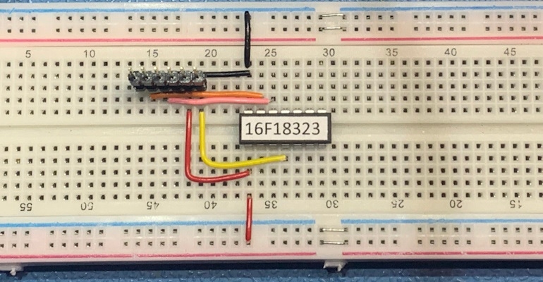
The great thing for hobbyists and prototyping is that PICs with 6 to 40 pins are usually available in both dual in-line (DIP or DIL) and surface-mount technology (SMT) packages. This means you can prototype a project by sticking a DIL packaged part directly into a breadboard as seen below, and then move to a smaller SMT device when you go into production.

Programming a PIC plugged directly into a breadboard. JOE FARR
The PICkit can be used to power the PIC during programming. It can even power a small project or evaluation board. The value of +ve from the PICkit is configurable to support whatever the PIC being used requires. The additional red and black wires connecting the PIC to the power and ground rails in the above image are there for when the programmer is removed, additional components are added, and we need to power the PIC from the breadboard.
As we noted earlier, in addition to +ve and GND, we need only three pins to program the PIC—Reset, Clock, and Data—all of which can be used as regular inputs or outputs when the PIC is in operation.
In the above example, my chum Joe Farr used a strip of 0.1-in. pitch header pins to connect a PICKit programmer directly into the breadboard and then run wires to the appropriate pins on the PIC. Now, that’s great for a PIC in isolation, but what about the case where you’ve been building up the prototype circuit around the PIC on the breadboard? You don’t want the PIC to attempt to power all the other devices forming the prototype circuit.
To address this issue, Joe has built a suite of little carrier boards to handle different size PICs. As we see in the image below, the PIC plugs into a socket on the carrier board, and the carrier board plugs into the breadboard so the PIC can talk to the rest of the circuit.

Programming a PIC plugged into a carrier board. JOE FARR
The carrier board also has a 6-pin header (only 5 pins are used here) that connects to the programmer. What you can’t see here is that there are a couple of surface-mount components (diodes, resistors, capacitors) mounted on the underside of the carrier board. These detect when the programmer is powering the PIC and automatically isolate it from the rest of the circuit on the breadboard. Pretty clever, huh?
Wow. I can’t believe I’ve waffled on for so long. In my next column, we will discuss setting up an environment in which to capture code at a higher level of abstraction than assembly language and then compile this code and program our PIC. Until then, as always, I welcome your comments, questions, and suggestions.
About the Author(s)
You May Also Like
Editors' Choice


Jun 4 - Jun 6, 2024
Jun 4 - Jun 6, 2024
Innovation in automation starts here. Discover and collaborate on automation solutions that are revolutionizing the entire production lifecycle — from design to production to market — and sharpen your competitive edge. ATX South is part of IME South, a six-in-one expo offering the latest insights & solutions spanning medtech, packaging, automation, plastics, design, & processing.
Register Now