Taming Rascally Mechanical Incremental Rotary Encoders
Feast your orbs on this cunning solution.
June 28, 2023
As you may recall, I am a man who wears many hats. For example, one of my roles is Chief Technical Officer (CTO) at LogiSwitch, where our mission is to debounce the signals coming from electromechanical switches (toggle switches, pushbutton switches, limit switches—you name it, we debounce it).
Just to ensure we’re all tap-dancing to the same drumbeat, when a switch is activated, its mechanical contacts bounce, making and breaking the connection anything up to 100+ times with a duration anywhere from a fraction of a millisecond up to 6+ milliseconds. This typically isn’t an issue with switches used to do things in human timescales like turning lights on and off, but it can cause problems with switches whose signals are being monitored (and acted on) by high-speed electronics like microcontrollers.
In a previous column, How to Keep a Flipped Switch from Bouncing Like a Golf Ball Dropped From the Roof, we discussed a variety of ways by which we can mitigate switch bounce. Traditional software solutions involve the use of counters or shift registers. Traditional hardware techniques include using RC delays for single pole, single throw (SPST) switches, and back-to-back NAND gates (in the form of SR Latches) for single pole, double throw (SPDT) switches.
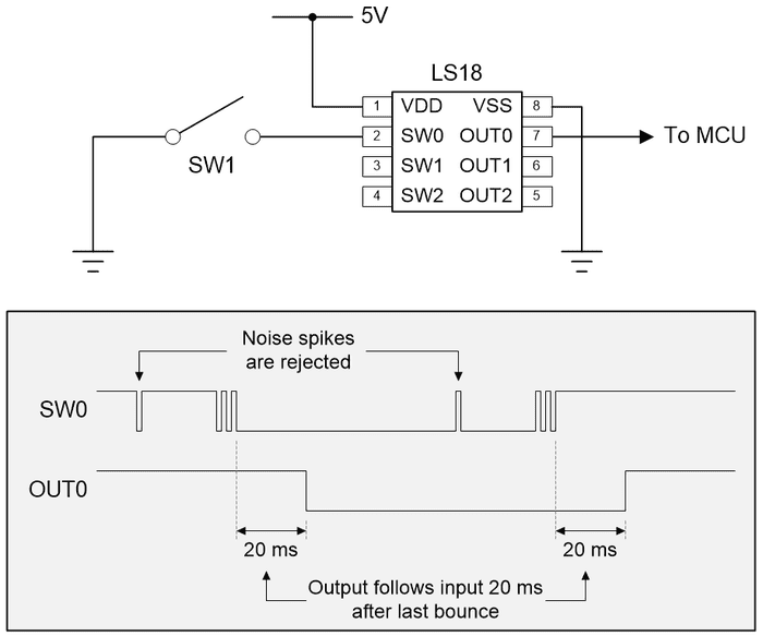
Of course, the solution we prefer is for people to use our LogiSwitch integrated circuits. In the case of SPST switches, we offer 3-, 6-, and 9-channel devices in both LTH (lead through-hole) and SMT (surface-mount technology) packages. Consider our 3-channel LS18, for example. In this case, any noise spikes are rejected, and the “clean” (debounced) output follows the “raw” (bouncing) input 20 milliseconds after the final bounce.
The reason I mention this here is that I recently received an email from one of our customers who we will call Michael (because that’s his name). Michael was attempting to use an LS18 to debounce the signals coming from a mechanical incremental rotary encoder and, not surprisingly, he was running into problems caused by the LS18’s 20-millisecond delays.
We discussed these devices in my Rascally Rotary Encoders column. The parts we are interested in here have two outputs called A and B along with a pushbutton switch output (in addition to rotating the encoder, you can also press it to activate its momentary pushbutton function).
When pull-up resistors are connected to the encoder’s A and B signals, the device commences with AB = 11. The term “detent” refers to a catch in a machine that prevents motion until it is released or overcome. Different encoders have different numbers of detents, which manifest themselves as tactile (inaudible) “clicks” as the knob is rotated. For example, the PEC11H series from Bourns are available with 16, 20, 24, and 30 detents associated with rotating the encoder through 360 degrees. The maximum rotational speed of these devices is 60 rpm (or one 360-degree rotation a second).
For the purposes of these discussions, we are focusing on encoders for which each detent is associated with what the data sheet refers to as a “pulse.” In reality, these devices employ a quadrature encoding scheme, which means that each “pulse” (“click”) involves the A and B outputs passing through a series of values. Commencing with AB = 11, one click clockwise will result in AB passing through 01, 00, and 10 before returning to 11 (A leads B). By comparison, one click anticlockwise will result in AB passing through 10, 00, and 01 before returning to 11 (B leads A).
Like so many things, this seems simple if you don’t delve too deeply. The problem is that, as we discussed in the aforementioned rotary encoders column, the mechanical versions of these devices are subject to switch bounce, which can really mess things up (the data sheet for the PEC11H series specifies a maximum contact bounce of 3 milliseconds at 60 rpm).
So, at this point we were posed with a conundrum. On the one hand, we could create a new LogiSwitch IC that could simply “clean up” the A and B (and switch signals). On the other hand, we could go one better and make life easier for Michael and other users by creating a super-duper LogiSwitch device we are calling the LS30 as illustrated below (we haven’t shown noise on the A and B inputs for simplicity, but the LS30 will handle any such noise like an Olympic champion).
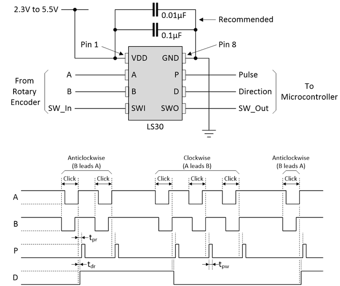
No external components like pull-up resistors (or resistors and capacitors used to implement RC filters) are required on the A, B, or SWI inputs. Having said this, it is recommended (although not mandatory) that a 0.1µF capacitor is connected between the power and ground pins (as close to the pins as possible) to compensate for any problems in the power supply. Also, it is suggested that a 0.01µF capacitor is connected between the power and ground pins (as close to the pins as possible) to filter any high-frequency noise, such as electromagnetic interference from other equipment.
The encoder’s pushbutton switch path (SW_In and SW_Out) behaves in the same way as the corresponding channel on the LS18. However, as opposed to simply debouncing the A and B inputs, we also process them to generate the P (pulse) and D (direction) outputs.
The D and P outputs perform their magic at the end of the cycle when A and B return to their 11 states. This allows us to handle cases when the user is rotating a bit too enthusiastically and overshoots a “click” (potentially starting a new cycle) before returning to the previous detent.
A 5-millisecond positive-going pulse on the P output indicates that an accredited rotational “click” has occurred. Values of 0 or 1 on the D output indicate clockwise and anticlockwise rotations, respectively. The D output will remain in its current state until the direction of rotation reverses, in which case it will transition prior to the pulse being presented on the P output.
The positive-going edge on the P signal can be used as an interrupt to the microcontroller to indicate that a “click” has taken place. The corresponding interrupt service routine (ISR) can then check the state of the D signal. Alternatively, the program can simply poll the P signal waiting for it to change, at which time it can read the value on the D input.
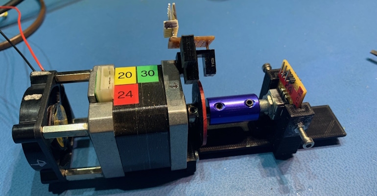
As usual, of course, things are never as simple as they first appear. In this case, the trick is to ensure that the LS30 is performing as required and that “X” clicks results in “X” pulses (not “X – 1” or “X + 1”). This is tricky if you are doing it by hand, so my friend Joe Farr with whom I collaborate on projects like this created the test rig shown below.
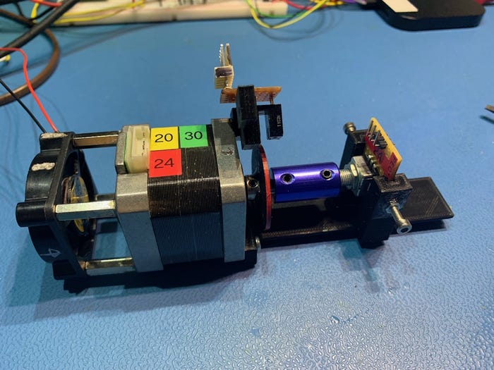
In the middle we have a stepper motor. On the left we have a cooling fan because the stepper motor can get hot if you’re not careful. On the right we have the rotary encoder connected to a breakout board (BOB) that also contains the LS30. The metallic blue connector links the motor’s shaft to the encoder’s knob.
Observe the 3D-printed disc just to the left of the metallic blue connector. The red edge indicates that this disk has 24 slots and is associated with a 24-detent encoder. Sitting about this disk (raised in this image to facilitate swapping the disk and encoder) is an infrared (IR) transmitter and receiver. We have other disks corresponding to different decoders as illustrated below.
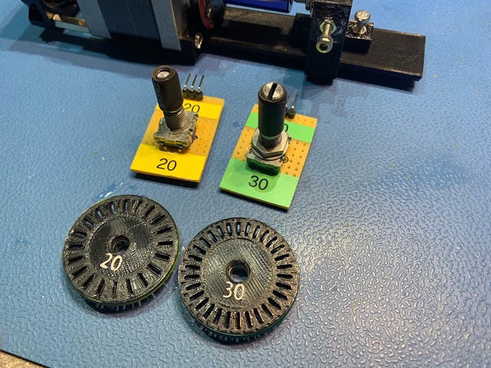
By means of the stepper motor, we can perform repeatable experiments, including varying the speed of rotation and adding acceleration and deceleration curves. Also, we can experiment with slightly overshooting a detent and then falling back. The reason for adding the optical encoder is that this allows us to cross-check the number of optical pulses with the number of pulses on our P output to ensure that everything is tickety-boo, as they say.
This is still a work in progress, and we have many more experiments to perform before we release this bodacious beauty into the wild (we did send Michael a couple of samples and he says that they have 100% addressed his requirements). I will let you know when we are ready to rock and roll in a future column. In the meantime, I’d be interested to hear your thoughts (you can comment below or email me at [email protected]), including any options, variants, or capabilities you think we should consider.
About the Author(s)
You May Also Like


