Mechanical Engineering Perspectives, Part 2: Creative Design Tweaks to Manage Speed, Cost, & Function
Here are a few mechanical engineering tips for optimizing prototype builds.

This is the second article in a 6-part series titled “Mechanical Engineering Perspectives for Efficient, Integrated Commercial Product Design.” When we think about product design, it’s common to immediately focus on developing what we see and experience in a product. While UX and UI design are critical to product success, the less-visible mechanical engineering functions can be the workhorse driving the innovation through to successful commercialization. Adam Smith, senior mechanical engineer at Product Creation Studio, has decades of experience designing and planning dozens of products for commercialization. In this series, Smith shares insights and tips on how mechanical engineering supports the transformation of product ideas into reality by working in sync with all disciplines throughout development.
Prototype builds are an important part of developing a product for commercialization. Unfortunately, schedule, cost, and manufacturability can limit or even prohibit building early and building often.
Waiting for a more mature design before using production manufacturing methods can lead to costly design iterations impacting budget and schedule. Coupling the knowledge of available rapid manufacturing methods with creative “design for prototyping” adjustments can allow you to build earlier and more often. With the advent of higher-quality, lower-cost, easier-to-use, in-house manufacturing tools, making the prototype yourself may be the most-efficient method.
This article shares examples and tips to help you think creatively about how to manufacture your design using prototype methods while still gaining crucial information required to vet your design for production manufacturing.
Discretize Your Design to Optimize Learnings
Splitting your assembly into logical subassemblies to facilitate prototype builds can help get around manufacturing limitations, resulting in clearer test findings.
Handheld tools, for instance, typically have a proximal user interface with distal end effectors and a transmission mechanism in between. Building the distal end on its own using 3D-printed metal parts in titanium or stainless steel can allow for mechanism analysis in days instead of weeks.
Focused assessment of each discrete mechanism can be easier to understand and iterate, optimizing those subassemblies for their own functions before joining them to the larger complicated assembly.
Economy of Scale
Building small-scale models of extremely large assemblies like skyscrapers and bridges has been around for ages. When designing extremely small assemblies, you can make large-scale prototypes using materials that mimic the properties of your tiny production-scale parts.
Small stainless-steel and titanium parts can be scaled up 10x to 12x and 3D printed in PLA or ABS plastic and behave much like the actual production metal parts. This allows for extremely fast iterative design, reducing the number of actual build-to-scale prototype iterations.
Minor scale adjustments can be quite effective as well. Adjusting shaft diameters and tubing diameters in your design to the closest readily available (McMaster-Carr) off-the-shelf materials makes it possible to assemble mechanism proof of concepts early on without waiting for production extrusions. Being a little lenient on exact specifications early on can speed the time to prototype significantly.

In-House Manufacturing for the Engineer’s Desktop
It’s difficult to beat the speed and flexibility of hand-shaved foam models for handheld device user interface mockups, but 3D-printed plastic parts can be a great solution for a rapid build of minor iterations/adjustments from one model to the next.
Most of us understand the value of 3D printing, and many of us know of low-cost, easy-to-use in-house desktop 3D printers (Prusa, Ultimaker, Raize, etc.) that build amazingly useful plastic parts, jigs, and templates, but there are a handful of additional technologies available for the engineer’s desktop that improve design and engineering visualization and reduce time to market.
Desktop laser cutters (Glowforge, Flux, OMTech) and water jet cutters (Wazer) can be extremely valuable for early mechanism prototypes, especially if the engineer is versed in designing flat shape assemblies (interlocking slots or tab and slot).
Using acrylic sheet and solvent bonding, complex mechanisms can be built and assessed in hours instead of days.
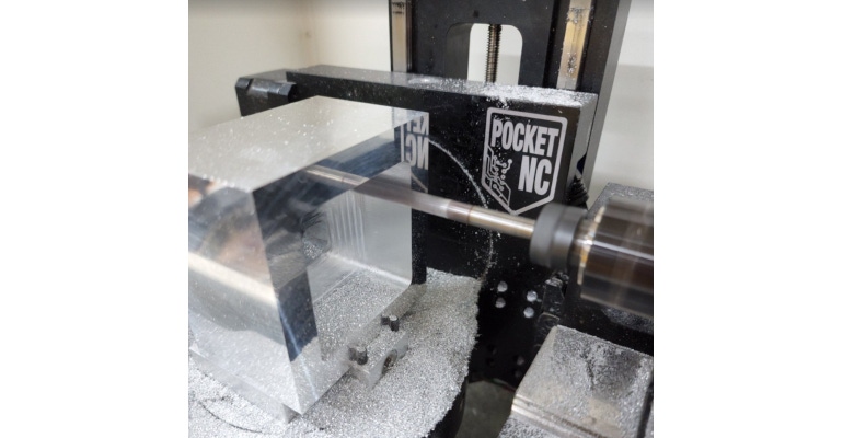
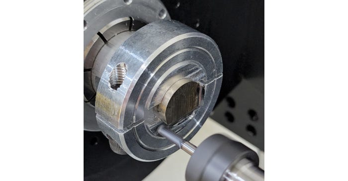
Another emerging market for designers and engineers is desktop milling. There are a handful of precision desktop mills (PocketNC, Bantam, HAAS) that allow for rapid milling of plastics and metals (including titanium and stainless steel) right on your desktop.

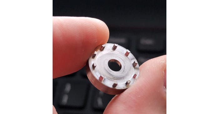
Using the 5-axis milling capabilities of the Pocket NC V2-10 and V2-50, I was able to build six iterations of a medical device in a couple of weeks versus four months. If I had outsourced the parts (six days), waited for them to arrive (two days), assessed function (roughly an hour), made the necessary adjustments (10 minutes), and requested updated parts (one more day), each iteration would take two weeks.
Using an in-house desktop mill, I was able to reduce the iterations to fewer than two days. You will likely find that having the tools immediately available drives you to use them more. Making a quick prototype to help others visualize your design intent, or to prove out a mechanical concept, becomes the norm instead of the exception.
Design for Information Early On
Although the end goal is a successful product, the path there is not exactly direct. Sometimes you need to take a step back and build for assessment of particular functions, rather than diving into the complete design all at once.
Being flexible and creative along the way, you can be more efficient at developing the “best” solution for your first product.
For other installments in this series, please see Mechanical Engineering Perspectives, Part 1: Material Costs, Function, & Durability and Mechanical Engineering Perspectives, Part 3: Quantity, Quality, and Time to Market.
About the Author(s)
You May Also Like


