An Introduction to Filters
April 1, 2013

People have asked for more information about analog and digital filters, so I'll devote a few columns to those topics. As taught to students in engineering schools, filters can seem like a math jungle. I'll take an intuitive and empirical approach and examine low-pass filters commonly used as anti-alias front ends for analog-to-digital converters (ADCs).
In an ideal low-pass filter, the output amplitude equals the input amplitude up to a cutoff frequency, fc, defined as the point at which the signal drops in amplitude by -3dB. As a signal frequency exceeds fc, the filter more sharply attenuates the output. The rate of attenuation vs. frequency, called rolloff, depends on the filter's characteristics.
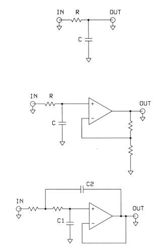
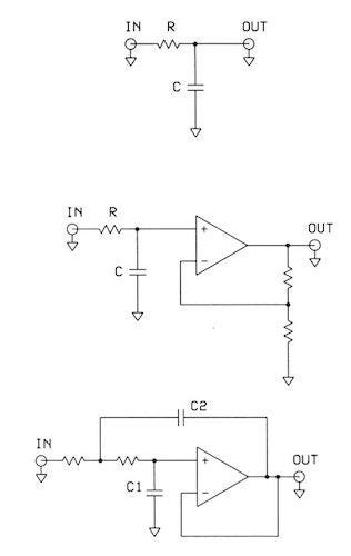
To start, look at the simple low-pass RC filter diagram. For DC and low-frequency inputs, the capacitor looks like an open circuit. As frequencies increase, the capacitor looks more like a short circuit to the high-frequency signals, which go to ground.

The output of the simple first-order RC filter can connect to an operational amplifier (op amp). The op amp acts as a buffer, often with a bit of gain. A first-order low-pass filter attenuates a signal at -20dB per frequency decade. The addition of a feedback capacitor to the 1st-order op-amp circuit gives you a 2nd-order filter that uses the Sallen-Key arrangement of components. A 2nd-order filter has an attenuation rate of 2 x -20dB or -40 dB/frequency decade. Each increase in filter order doubles the rolloff.
An intuitive look at the Sallen-Key circuit reveals its operation and simplicity. This circuit has an RC circuit at the op-amp input, and capacitor C1 provides a low-impedance path to ground for high-frequency signals. With little or no signal reaching the op-amp input, the op-amp output looks like a virtual-ground connection. Capacitor C2 then looks like another low-impedance path to ground for high-frequency signals.
Unfortunately, we cannot easily build a 3rd- or higher-order filter with operational amplifiers (Ref. 1). But we can cascade 1st- and 2nd-order filters, and the orders add. So two 2nd-order filters in series provided a 4th-order filter, with a rolloff of 4 x -20dB, or -80dB/decade.
Second-order filter equations include a damping factor, a, that determines the shape of the filter cutoff. By changing this value when calculating the resistor and capacitor values, you can adjust the shape of the frequency-response graph as needed. Thankfully, many filter-design computer programs already account for this factor when you choose a filter type -- Butterworth, Bessel, or Chebychev, for example.
For more information:
Microchip Technology offers free FilterLab software, search for FilterLab.
Online filter-design tool.
Find equations for a Sallen-Key filter here.
Reference:
Berlin, Howard M., Design of Active Filters with Experiments, Howard W. Sams and Co., 1977. ISBN: 0-672-21539-X.
Related posts:
About the Author(s)
You May Also Like
.jpg?width=300&auto=webp&quality=80&disable=upscale)


