Theremin? Bleh! Therebone? Yeah! (Part 1)
Introducing the soon-to-be-legendary therebone.
March 8, 2023

What instrument would you wish to own if you were to be offered a free pick? I think it’s fair to say that none of us are immune to the seduction of a sarrusophone. For myself, however, I would love to take possession of a glass armonica of the type invented by Benjamin Franklin in 1761.
The operating principle underlying the glass armonica is similar in concept to filling a wine glass with water, wetting your finger, and then running your finger around the rim of the glass while applying just the right amount of pressure to elicit an eerie tone. In the case of the glass armonica, however, this little scamp involves 36 concentric glass bowls that are rotating. Applying one or more wet fingers to the spinning bowls results in corresponding notes whose eldritch tones send shivers up (and down) your spine.
The glass armonica was no toy. In fact, musical luminaries such as Mozart and Beethoven composed chamber music for it. This video shows a glass armonica in action. As I say, I would love to own one of these bodacious beauties, but their starting price is close to $8,000, which puts them about $7,900 outside my price range.
If you like the unearthly tones of the glass armonica, then another classic is the theremin, which is named after its inventor, Leon Theremin, who patented the device in 1928. Have you ever watched the British crime drama television series, Midsomer Murders? If so, you’ll have noticed that, as shown in this video, the spooky theme tune features a theremin being played by Celia Sheen.
You can purchase pre-built theremins in all shapes and sizes for anything from $99 to … the sky’s the limit. There are also myriad kits available. For a beginner, I quite like the look of the MicroKits Theremin, which is breadboard-based (no soldering) and available on Amazon for $39.95. Alternatively, I was just chatting to David Levi (the Inventor and Owner of MicroKits), who says he would really appreciate folks purchasing directly from his MicroKits.net website (I just bounced over there, and now I want a Synth-a-Sette sound synthesizer also).
But that’s not what I wanted to talk to you about (although you can bet your little cotton socks that the melancholy sound of the theremin will return to haunt us before this article is done).
I write a monthly "Cool Beans" column for Practical Electronics, which is the UK’s premier electronics and computing hobbyist magazine. Recently, the publisher, Matt Pulzer, said that he had been receiving a lot of requests for articles introducing the Arduino for absolute beginners. Many of the requesters are 70-to-80-year-old retired engineers who have experience with electronics in general but not with microcontrollers.
You may think this is strange, but I’ve met people who used to sport black belts when it came to designing circuits using vacuum tubes (which make my brains leak out of my ears), but who couldn’t wrap their brains around circuits based on discrete transistors. Similarly, I’m acquainted with crusty old analog engineers who can whip up a circuit using transistors, capacitors, inductors, and resistors before you can say otorhinolaryngologist (we all know you are going to look this up to see if it’s a real word), but who are completely confounded by the concepts embodied by SN7400-series primitive logic integrated circuits (IC).
But we digress... As a result of my conversation with Matt, I’m currently writing a series of articles under the umbrella name of "Arduino Bootcamp." Matt told me that he wanted this series to focus on “hands-on.” He also told me to assume that the readers already knew basic concepts like voltage, current, and resistance. Based on past experience, however, I hate to assume anything, so—just in case Matt was wrong—I included a link in Part 1 of the series to an aptly-named blog, "What Are Voltage, Current, and Resistance?," which points to a collection of online articles I’d already written.
Similarly, Matt told me we could be reasonably confident that the readers would know how breadboards work. The thing is that if you know something yourself, you tend to unconsciously assume everyone else knows the same thing. In the case of breadboards, I’ve met a lot of people who aren’t as knowledgeable as one might hope, so I quickly penned an "Arduinos and Solderless Breadboards" column on my own Cool Beans Blog.
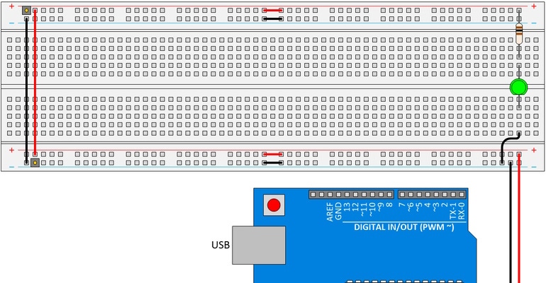
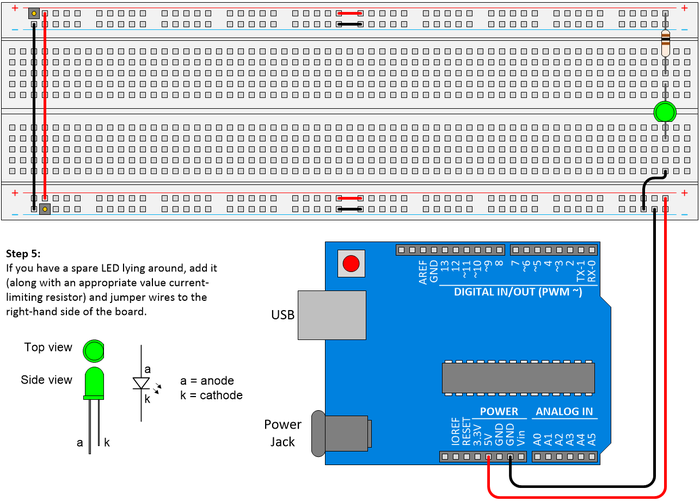
In this blog, after explaining how a breadboard is wired inside, I discussed how I go about setting up my own breadboards as shown below. I start by connecting my power and ground sources to the rails in the lower right-hand corner of the board. Next, I move to the left-hand side of the board and link the power and ground rails on the bottom to their counterparts at the top. Finally, I return to the right-hand side of the board and add a light-emitting diode (LED) along with its current limiting resistor.

What about the two links in the middle of the power and ground rails at the bottom of the board, and similarly at the top of the board? Well, some breadboards have split power and ground rails, which is great if you wish to use multiple power supplies like 5 V for one part of your circuit and 3.3 V for another part of your circuit. In such a case, the blue and red lines associated with the rails usually have breaks to reflect this split … but not always!
I learned this to my cost many years ago. I couldn’t understand why a relatively simply prototype circuit wasn’t functioning as expected. Since it never struck me that my breadboard’s power rails weren’t connected all the way across, it took me an inordinate amount of time to track the problem down. As a result, I now include these links as a matter of course.
Returning to the layout shown above, when I power-up my Arduino and the LED on the right-hand side of the breadboard starts to glow, this tells me that I have power to my breadboard and gives me a high level of confidence in the integrity of my board’s power rails. Any day that includes a glowing LED is a good day as far as I’m concerned, and we haven’t even got to flash one yet (as I always say, “Show me a flashing LED and I’ll show you a man drooling”).
“But what’s any this got to do with theremins?” I hear you cry. I’m glad you asked. Just to get everyone’s juices flowing, I started my "Arduino Bootcamp" series with a couple of experiments based on individual LEDs, but we quickly transitioned to using a 7-segment display.

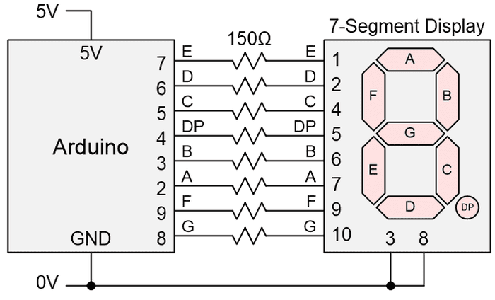
Currently we are using a single-digit common cathode 7-segment display. Also, we’re using eight of the Arduino’s digital I/O pins to control it. Eventually, we are going to move to using two displays, then four, but that’s a topic for another day.
If we were to ask as to range of numbers we could present using this display, many people would have the knee-jerk reaction “0 to 9,” but they would be wrong (and I’m not talking about hexadecimal). Suppose we wish to repeatedly display a value like 1957 (the year I decided to grace this planet with my presence), for example. We could do this by flashing the numbers in series with a slight delay between adjacent digits and a longer delay between sequences: 1-9-5-7 - - - - 1-9-5-7 - - - - 1-9-5-7 etc.
I’m also planning to use this as a platform to teach the readers about different sensors, like light-dependent resistors (LDRs) and thermistors. In each case, in addition to using tools like the Serial I/O window to present the values being detected, we will also present these values on our 7-segment display.
One of the devices I’m planning on demonstrating is a classic ultrasonic range sensor, like the HC-SR04, which can provide a 2- to 400-cm non-contact measurement function with an accuracy of around ±3 mm. I’m also planning on using the Arduino’s tone() function to play simple tunes on a small loud speaker with a 1-transistor amplifier.
Then it struck me that I could combine the two, using the reading from the ultrasonic rage sensor to control the frequency of the note being played (on the speaker) and displayed (on the 7-segment display). But what should we call such an instrument?
Unlike Leon Theremin, who audaciously named his cunning contraption after himself, I feel that calling an instrument a “maxfield” doesn’t have quite the ring or set the right tone (I’m too punny for my own good).
Deep in the mists of time, while I was a high school student in the UK, I used to play the trombone in a multi-school orchestra (“Not a lot of people know that,” as the British actor Sir Michael Caine is mistakenly credited as saying). Leon may have his theremin, but I shall take the music world by storm with my therebone (and that’s not something you expect to hear yourself saying on a daily basis)!
I shall reveal more in Part 2 of this 3-part mega-mini-series. In the meantime, as always, I welcome your captivating comments, insightful questions, and shrewd suggestions regarding anything we’ve discussed in this column.
About the Author(s)
You May Also Like


.jpg?width=300&auto=webp&quality=80&disable=upscale)


