Design Decisions: What Designers Need to Know About EMI Shielding
December 5, 2012

For OE designers of today's advanced electronic equipment, two growing equipment protection concerns are thermal management and shielding from electromagnetic interference (EMI). Unfortunately, protection in one area often means forfeiting some performance in the other.
A completely sealed, shielded enclosure would ward off EMI across a wide range of frequencies. However, the need for airflow means there must be openings in the enclosure, which means opportunities for EMI. To prevent EMI while maintaining airflow, the enclosure designer must find a happy medium by selecting the proper EMI filter at the fan exhaust. EMI filters often take the shape of a honeycomb. The size (or waveguide) of the openings affects both airflow and shielding effectiveness, so waveguide is a very important design decision.

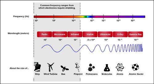
This image compares EMI wavelengths to recognizable objects. On one end of the spectrum, a radio wavelength is comparable to the length of the Titanic. On the other end, the wavelength of an X-ray is comparable to the length of an atom. This is why an X-ray can travel through skin (just as an atom could) but not through dense lead. Similarly, a radio wave can travel through the air but could not be received inside a car without the use of an antenna.
These same principles can be applied to the size of the honeycomb. The larger the openings are, the more susceptible the electronics are to longer wavelengths and lower frequencies of EMI. However, the smaller the openings are, the more airflow will be impeded. Fortunately, adding depth to the openings (the thickness of the filter) improves shielding effectiveness without greatly impeding airflow. Furthermore, certain materials offer more effective shielding than others but are much more expensive (e.g., copper versus aluminum), which can drive up cost significantly for high-volume products. It's a balancing act between cost, airflow, and shielding, and finding the perfect balance for your equipment first requires you to identify the tolerable operating parameters.
As it applies to filter selection, we must look at both the temperature range and the EMI frequencies related to equipment performance.
If the OE electronics designer can identify the ideal temperature range, the enclosure designer can use the wattage of the equipment to determine waste heat generated, as well as the estimated ambient temperature, in order to recommend the proper fan size in terms of cubic feet per minute (CFM) of air moved. The enclosure designer would then subtract the amount of static pressure lost due to the impediment created by the honeycomb. If the resulting CFM output were determined to be sufficient for the temperature range, and the honeycomb waveguide were small enough to limit the frequencies that could put the equipment in danger, the balancing act would be successful.
This is just one example of how enclosure designers can help OE designers protect their equipment with common-sense solutions. As electronic equipment becomes more demanding and is subjected to harsher environments, it's becoming increasingly important for OE electronics designers to collaborate with enclosure designers throughout the design process.
Related posts:
About the Author(s)
You May Also Like


.jpg?width=300&auto=webp&quality=80&disable=upscale)
