University of Washington Students Create Award-Winning Motorsports PCB Design - Part Two
July 8, 2015

This is part two of an article discussing the University of Washington's nationally ranked FSAE electric and combustible cars. Both cars required several printed circuit boards, which Sierra Circuits helped design and manufacture. The UW team assembled their boards in-house.
Part one covered UW's process, which included working on the car's design, manufacturing, assembly, and testing for an entire year. We also discussed the challenges we faced, design goals, and general characteristics our boards required.
PCB Showcase: Four Boards
The following boards were crucial for our cars to function:
1. Accumulator Indicator Light (AIL) and Tractive System Active Light (TSAL) Driver board
2. Precharge/Discharge Module board
3. Brake Plausibility Check (BPC) board
4. Insulation Monitoring Device (IMD) Latch board
Below, we'll showcase the objectives of each PCB, describe our design and manufacturing challenges, and explain the testing and revisions we performed to prepare the boards for race day.
1. Accumulator Indicator Light & Tractive System Active Light Driver


Objectives
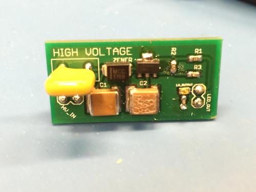
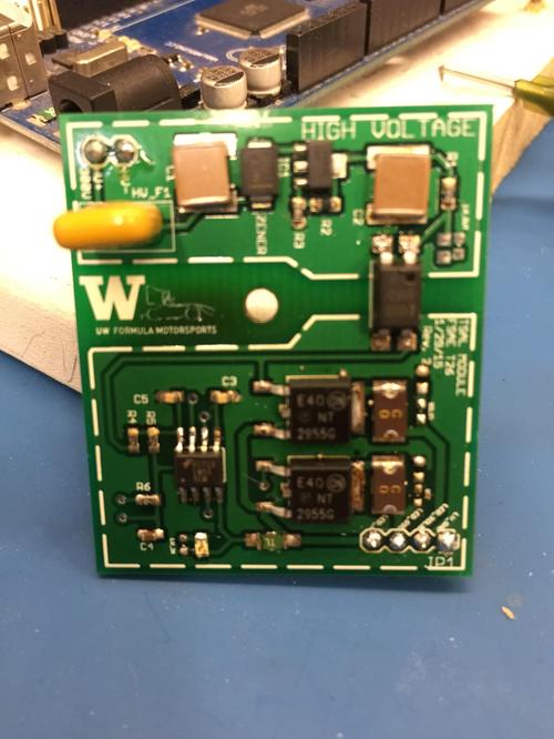
We designed two similar boards: the Tractive System Active Light (TSAL) and Accumulator Indicator Light (AIL). These would serve as indicators when high voltage (defined at 60V) was present in the system. The TSAL needed to flash between 2 Hz and 5 Hz to indicate that the tractive system had high voltage. The AIL was a single solid light that illuminated when the battery pack was turned on.
The competition rules dictated that the high and low voltage sides of our boards must have at least 3 mm of space between them and be galvanically separated. On the TSAL module, we did this with an opto-isolator. The rules also mandated that the boards should have no modified programmable components.
Both boards had a high voltage PTC fuse and decoupling capacitor next to the input. We tuned a linear regulator to regulate the voltage to the low voltage side of our board. In order to regulate only high voltage currents, we also added a 60W Zener diode before the regulator. From that point in the circuit, the AIL module ran a module to the light, and the TSAL module had an opto-isolator to the low voltage side of the board. We supplied 12V to the low voltage side of the board from our DC/DC converter and used p-fets to supply power to the light when high voltage caused the opto-isolator to switch. We had two p-fets; one continuously supplied power and put out a constant high voltage, while the other supplied voltage from a 555 timer adjusted to output at ~3 Hz.
Challenges
The first challenge we faced was to design the boards to be as small as possible, and the second was to regulate any voltage from 60V-300V to 24V.
Testing and Revisions
We tested the board by connecting it to two adjustable power supplies. We ensured the board operated as it was intended to as we adjusted voltages. We also monitored the temperature with an IR gun and ran brownout tests on each board. The tests on our first revision showed that both boards got uncomfortably hot, so we made the bottom plane of the boards a heatsink for the linear regulators and populated the pad with vias to dissipate the heat. Earlier in the process, we also switched to using p-fets instead of n-fets and a NOR gate to shrink the size of the board.
About the Author(s)
You May Also Like


