Sign up for the Design News Daily newsletter.
You can use a DC motor in all sorts of DIY projects. But why go out and buy a DC motor controller when you can build one yourself? Gadget Freak Paul Rako shows you how.
October 31, 2016
10 Min Read
.svg?width=850&auto=webp&quality=95&format=jpg&disable=upscale "A Quick-and-Dirty DC Motor Controller")
Years ago my pal Steve Titus wanted to experiment with some drone rotor designs. He needed a simple motor controller that could operate from 8V to 12V and deliver amperes of current to a DC motor used in radio-controlled aircraft (figure 1).
I whipped out a design based on the classic TL494 PWM (pulse width modulation) chip (figure 2). This Texas Instruments chip is second-sourced by ON Semi, as well as others. Distributors carry the chip in small quantities with pricing from 24 cents in 1000s to 60 cents each (2016). I learned to love this chip when I consulted to Teledyne. I designed power supplies for radar jammers on F-16 fighter jets. The TL494 came in a ceramic DIP package so you could use it on mil-spec projects or for ultra-reliable industrial applications. These days I would design in an SOIC for the small size and vibration resistance. The part even comes in TSSOP for micro-miniaturization.
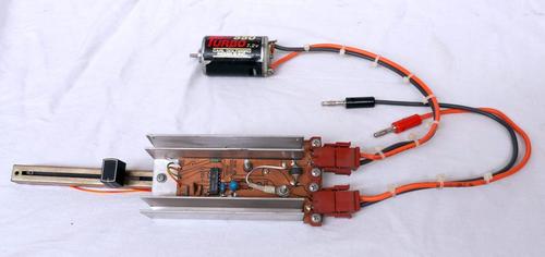
Figure 1: You connect this motor speed control to a 12V battery. It can supply 15A of current to a DC motor.
Figure 2: The TL494 PWM chip is a general-purpose building block for a dozen switching power topologies. VCC can range up to 41V and it has a 5V reference output. (Source: Texas Instruments)
To get the large amperage Steve required, I had the chip drive a large TO-3 metal-can PNP Darlington transistor that can handle 100V and 16A. Since the inductance of the motor and the wires connected to it could generate switching spikes even higher than 100V, its necessary to put a robust clamp diode across the motor (figure 3).
Figure 3: A TL494 chip combined with a power Darlington transistor can deliver 16A of current to a load such as a DC motor.
Figure 4; The circuit applies pulses to the motor (red). This is based on the control voltage reaching a set threshold (yellow). The current into the motor gets up to 4 Amperes, and then falls through the off-time (green) . Small oscillations in current are due to the inductance of the motor and wiring interacting with the capacitance of the snubbing diode.
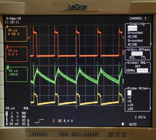
Figure 4: The circuit applies pulses to the motor (red). This is based on the control voltage reaching a set threshold (yellow). The current into the motor gets up to 4A, and then falls through the off-time (green) . Small oscillations in current are due to the inductance of the motor and wiring interacting with the capacitance of the snubbing diode.
You effect motor speed control by chopping the DC input voltage into variable-width pulses. I picked C3 and R5 to give an operating frequency of 8.7kHz. If the IC doesn't chop at all, it applies full battery voltage to the motor. If it applies brief narrow pulses to the motor, the average voltage is low, and the motor runs slowly (figure 4). With pulses that are vanishingly narrow there is no voltage applied to the motor, and it stops rotating. With no load on the motor, the voltage waveform can look squirrely as the back-EMF (electromotive force) of the motor creates voltage as a generator.
 Designers & Innovators. Learn more about some of the latest designers and innovators and what they're up to at ESC Silicon Valley, Dec. 6-8, 2016 in San Jose, Calif. Register here for the event, hosted by Design News’ parent company, UBM.
While it might appear brutal to apply these pulses to the motor, remember that motors run on magnetism and magnetism is made with current, not voltage. So while the controller apples voltage pulses, the motor inductance turns this into current ramps that are proportional to the voltage.
For mechanical design I bought some heat sinks at a salvage yard that were already drilled to mount a TO-3 transistor. I used mica insulators and thermal grease when I mounted them. The studs from the transistor mount also spaced off and mounted the circuit card. I also picked up some 10 kilo-ohm slide pots at the salvage yard. I laid out the board in ProCAD. To make the circuit board I used pre-coated boards that I applied transparencies from my laser printer. Once the photo-resist was exposed, I plopped them in a tray of heated ferric chloride.
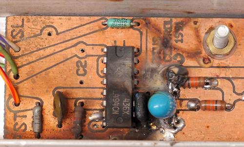
Figure 5: My non-engineer buddy didn’t think that the polarity of the input mattered. This is what happens when you hook the battery wires backwards.
Regrets, I've had a few. Today I would use a surface-mount chip, and not use any tantalum or electrolytic capacitors for the best reliability. There is no other way to get the power of a TO-3 transistor on a big metal heatsink. But this was a tremendous over-design. Next time I would look at using a low-on-resistance MOSFET so I would not need the metal heatsink or the TO-3 case. A surface mount D2PAK is equivalent to a TO-220 package, and soldered to a hand-sized circuit board should be able to take away the heat. Big downside here is that the circuit board would not be isolated from the transistor drain, so maybe a TO-220 or TO-3 case with an insulator would still be a good idea.
I also would just order the PCB from a decent quick-turn fabrication shop rather than messing with photo-resist PCB material and transparencies and ferric chloride. At some point it is just easier to have the boards made, especially now that I know the basic design works OK.
Another regret I learned the hard way. I once designed a prototype with salvage yard parts to get it to the customer as soon as possible. He loved it and asked for 50 more. When I went back to the salvage yard they did not have those quantities available. They had no idea where to get more of the same parts. Now I stick with main-line distributors like Allied, so I know I can get as many parts as I need, they are not counterfeit, and my fellow engineers and hackers can order the exact same parts. Reproducibility is an essential part of the scientific method. The BOM (bill of material) below has available parts rather than the salvage yard heatsink and pot and other parts in this prototype.
My final regret is not making it really really clear to my friend Steve that everybody knows the red wire goes to the plus terminal of the 12-volt battery. He promptly hooked it up backwards and blew up one the prototypes before any use (figure 5). Thankfully I have learned to make 3 prototypes. Two that I can compare design changes and one that Marketing steals and ships to a show in Kirghistan.
Click here to download the full build instructions, including ProCAD PCB files as well as DXF and DWG versions.
Do you have a cool, original, homemade gadget collecting dust in your garage? Give us the details at DesignNews.com/GF, and you may receive $500 and entry into our Gadget Freak of the Year contest!
DC motor controller PARTS LIST | |||
Component reference | Component/Material | Cost | Source |
Motor | Motor, DC Ceramic Permanent Magnet, Long Stack - Ball Bearings, 24 VDC | $127.07 | |
Q1 | TRANSISTOR, NTE250 PNP SILICON DARLINGTON 100V IC=16A TO-3 CASE | $8.74 | |
Q1 insulator | RS Pro Heatsink Transistor Mount Kit For TO-3 | $1.83 | |
Q1 grease | Aavid Thermalloy Thermal Grease, 2 Oz., Thermalcote | $10.82 | |
PCB | MG Chemicals Board; Copper Clad; 9 x 6 in; 1/16 thk; double sided; presensitized | $21.50 (makes 4 PCBs) | |
PCB etchant | MG Chemicals Chemical; Ferric Chloride Copper Etchant; 17oz liquid | $9.25 | |
D1 | Diode, MR752 6A 200V Silicon Rectifier | $1.14 | |
U1 | TL494 SWITCHMODE Pulse Width Modulation (note- SOIC package!) | $0.27 ea (20 min) | |
Pot1 | Bourns Potentiometer, Panel Control, Carbon, 100mm, 10 Kilohms, 20% | $3.91 | |
Pot knob | RS Pro Slide Knob; Body: Black with a White Indicator; 1.2x4mm Shaft | $0.39 | |
Heatsink | Wakefield 423K Heatsink; TO-3; 47C @ 50W; 2.625 in.; 0.5C/W; | $20.79 | |
C1 | Capacitor; Tantalum; 33uF; Tap Series; Radial; Case J; 10%; 25V; 33VDC; 1.2 Ohms ESR | $2.18 | |
C2 | Capacitor; Ceramic; Cap 1uF; Tol 10%; Radial; Vol-Rtg 25V; Dielectric X7R | $0.770 | |
R1. R2 | Vishay Dale Resistor; Metal Film; 133 Ohms; 0.5 W; Tol 1%; Axial; Military (qty 2) | $0.44 ea | |
R3 | RESISTOR METAL FILM 1/4W 3.16K OHM 1% AXIAL LEAD | $0.05 | |
R4 | Resistor; Metal Film; Res 1.13 Kilohms; Pwr-Rtg 0.125 W; Tol 1%; Axial | $1.02 | |
C3 | Nichicon Capacitor Polyester Film Cap 0.01uF 100V 10% Radial 6.5X10.5 LS 5mm | $0.142 | |
R5 | Vishay Dale Resistor; Metal Film; Res 19.1 Kilohms; Pwr-Rtg 0.125 W; Tol 1%; Axial; Military | $0.09 | |
J1, J2 | TE Connectivity UNIV M-N-L HEADER, 02P UMNL HDR ASSY R/A 94VO LF | $1.66 ea (qty 2) | |
P1, P2 | TE Connectivity Connector, Soft Shell; Universal MATE-N-LOK; 2; Plug; Nylon; White; 19 A | $0.25 ea (qty 2) | |
P1, P2 contacts | TE Connectivity Universal MATE-N-LOK II Socket Contact, 24-18AWG, Gold (30) over Nickel | $1.26 ea (qty 4) | |
P3 | Pomona Electronics Banana Jack; Banana Plug; 15 A; Black; Beryllium Copper; 5000 Vrms | $5.24 | |
P4 | Pomona Electronics Banana Jack; Banana Plug; 15 A; Red; Beryllium Copper; 5000 Vrms | $5.24 | |
Q1 screws | APM Hexseal Hardware, Phillips Pan Head Seelskrew, 1 Inch, 6-32 Thread Size, SS | $0.51 ea (qty 2) | |
J1, J2 screws | APM Hexseal Hardware, Phillips Pan Head Seelskrew, 1/2 Inch, 6-32 Thread Size, SS | $0.43 ea (qty 4) | |
Q1, J1, J2 nuts | Keystone Electronics Nut; Hex 6-32 Threaded ; Steel; Machined; OD .250 | $0.070 ea (qty 10) | |
Q1, J1, J2 lock washers | Keystone Electronics Terminal Lug; Lockwasher; Brass, Tin Plate; Length .875; Hole Size #6 | $0.120 ea (qty 6) |
[All images via Paul Rako, unless otherwise noted]
You May Also Like
Editors' Choice


Jun 4 - Jun 6, 2024
Jun 4 - Jun 6, 2024
Innovation in automation starts here. Discover and collaborate on automation solutions that are revolutionizing the entire production lifecycle — from design to production to market — and sharpen your competitive edge. ATX South is part of IME South, a six-in-one expo offering the latest insights & solutions spanning medtech, packaging, automation, plastics, design, & processing.
Register Now