Keep an Eye on Hydraulic Transmission Lines
November 7, 2013

In applications where large forces/torques are required, with a fast response time and high accuracy, hydraulic control systems are essential. They have a more competitive power-weight ratio than electrically actuated systems, which are limited by magnetic saturation. The hydraulic medium is also mechanically stiffer than the electromagnetic medium. Self-lubrication and inherent heat transfer are added advantages. Fluid power applications are numerous and all are multidisciplinary systems that require a systems approach to design and implement with optimal energy consumption. Hydraulic valves, pumps, motors, cylinders, and accumulators are all routinely modeled and analyzed. Often overlooked in a hydraulic control system are the hydraulic transmission lines. Failure to model their dynamic effect could lead to poor performance and possible instability.
The hydraulic transmission line is a distributed system. The motion of the fluid in the transient condition takes place under the action of fluid inertia, friction, and compressibility, as well as the driving pressure forces. Fluid velocity, pressure, and temperature vary from point to point along the pipe/hose length and radius, which may themselves be compliant. A lumped-parameter model, which describes the dynamic behavior of the transmission line with acceptable accuracy, is needed.


It is insightful to use the electric-hydraulic analogy to develop and understand the lumped-parameter model. The effort variables are electric voltage and fluid pressure, while the flow variables are electric current and fluid flow rate. Energy is stored via the effort variables in the electrical capacitor and fluid capacitance. Energy is stored via the flow variables in the electrical inductor and fluid inertia. Energy is dissipated in the electrical and fluid resistance elements. Fluid resistance and fluid inertia are generally well understood. Fluid capacitance is due to the bulk modulus (measure of fluid compressibility) of the fluid, which is reduced by entrained air and the compliance of the flexible hose. The analog RLC electrical circuit is shown. The input-output matrix is derived by applying Kirchhoff's Laws, applicable to both electrical and hydraulic circuits.
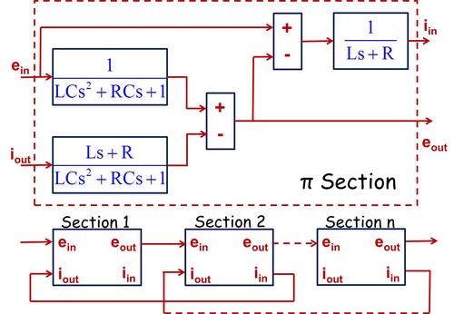
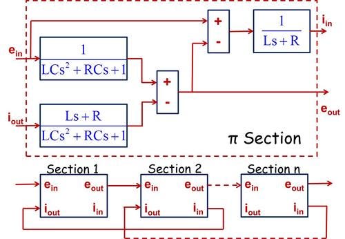
A block diagram for one lumped element, called a π section because of its circuit shape, is shown. This applies to both the electrical and hydraulic circuits. This is easily implemented in MatLab/Simulink and gives insight and understanding. The greater the number of sections used, the closer the dynamic behavior prediction is to that obtained from the distributed-parameter model to the actual system behavior.
How are the hydraulic resistance, inertia, and capacitance determined for each section of the transmission line? Simplifying assumptions are used, e.g., laminar, unidirectional flow for resistance; lump of fluid as a rigid body for inertia; and system bulk modulus (fluid, entrained air, and flexible hose) for capacitance. Hydraulic transmission lines, like electrical transmission lines, can be modeled in a lumped-parameter way and combined with models of other components to predict dynamic response and stability and for control design.
Related posts:
About the Author(s)
You May Also Like


