October 17, 2014

In the linear motion world and with the trend to systems that require higher accuracy and repeatability, we often field questions such as "how accurate is the actuator?" In an attempt to answer, we will most often need to get to a basic understanding of the specifications and to what the specifications are really referring. You see, there is way more involved in this understanding than simply stating a number.
First of all, we need to set the stage for the conversation of exactly what parameter we need to specify. Accuracy refers to the ability to achieve a commanded position, or better said, the error in commanded position versus the actual position achieved. The error then relates to the stated accuracy. However, errors in a single-axis system can come from several sources. So to break this down even further, we need to consider the mechanical actuator itself, the motor and its encoder, and the motor driver, as each of these elements of a linear actuator system have an influence on accuracy and repeatability. This article will discuss the mechanical actuator platform of a rodless actuator built with commonly available mechanical components.

The motion control coordinate system
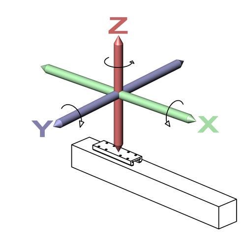
Linear actuator hardware may experience errors in six degrees of freedom. Many times this is referred to as the motion control coordinate system. So the machine designer must first understand if the possible errors are important in only one degree of freedom, or if the goal is to accurately position the device to some point in three-dimensional space, which includes all possible degrees of freedom. One way to simplify understanding this is to consider an actuator lying flat on a table. The motion errors that may occur could be in the direction of up/down, which would be the Z-axis; side-to-side, which would be the Y-axis; and end-to-end, which would be the X-axis. Rotation about these axes makes up the remaining three degrees of freedom -- for a total of six.
Six degrees of freedom
Considering all the possible sources of errors and what they represent as application parameters can be quite confusing. When linear motion occurs, the actuator travels through its length of stroke as determined by the components and methods used in its construction.
Linear actuators need to have some type of structure upon which the actuator components are mounted or attached. This may be aluminum, steel, or as in some very high precision devices materials such as granite. Some actuators are created using extruded aluminum profiles and others may utilize components machined to various degrees of precision. To this structure, the driving components are attached such as lead screws or timing belts along with the appropriate hardware to assure proper function. In the case of an actuator that is intended to carry or support loads such as a tooling fixture or end effector there will also be some load-carrying components such as bearing rails and bearings. These fundamental components are the basis of the "actuator." Now, let's have a look at where possible errors could come from.
Accuracy and the linear actuator
All mechanical devices/components have possible tolerances (dimensional and geometric) associated with manufacturing them. While the worst possible case -- where all tolerances are at a maximum -- rarely exist, it's important to take all possible tolerances into consideration for a complete understanding of the system and evaluation of possible errors.
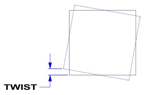
Consider a 12-inch stroke actuator that is manufactured using an extruded aluminum profile and linear ball bearing rails driven by a ball screw. Starting with the extruded aluminum profile, we know that the extruded profile will require some manufacturing tolerances. These tolerances relate to feature size, as well as bow and twist.
About the Author(s)
You May Also Like


