Mobile Robotics Kit Teaches Coding and Electronics Skills
Educators are incorporating robotics into their STEM and CTE curriculum to train the new skilled workforce of engineers and technicians. This skilled workforce will be responsible for designing and maintaining advanced robotic systems.
June 19, 2017

Robotics is making a major impact on how we work, play, and learn. Al, automation, and robots are hot trending topics discussed in trade publications and online news feeds. According to IDC (International Data Corporation) the robotics industry and associated partners will reach $135.4 billion by 2019. IDC’s research also showed international robotics spending was $71 billion in 2015 and is expected to grow at rate of 17%.
The global educational robotics industry is forecasted to grow at a CAGR (Compound Annual Growth Rate) of 21% by 2020, according to Technavio’s market research. Educators are incorporating robotics into their STEM and CTE (Career-Technical Education) curriculum to train the new skilled workforce of engineers and technicians. This skilled workforce will be responsible for designing and maintaining advanced robotic systems. Key vendors in the educational robotics market are exploring mobile technologies to enable classrooms to experience a rich learning environment. Some of these key vendors include but not limited to are:
Fischertechnik
Lego
Modular Robotics
Roboshop
Tetrix Robotics
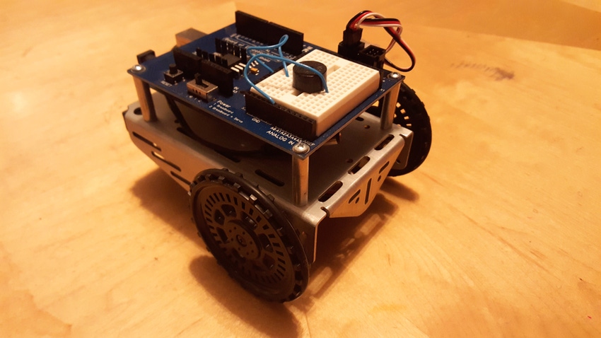
Another educational robotics vendor that provides a low cost kit for K-12 classrooms, colleges, and universities, and individuals is Parallax Inc. Parallax provides a mobile-based robotics platform called the BOE (Board of Education) bot that allows a variety of coding and electronics technology skills to be acquire with this kit. The BOE bot shield provides the electrical interface between the mobile base servo motors, breadboard sensors, and electronics to an Arduino microcontroller development platform.
Mobile Robotics Kit Teaches Coding and Electronics Skills |
The Parallax BOE bot kit allows coding and electronics technology skills to be acquired in an education-friendly environment. (Source: Parallax Inc.) |
The Parallax BOE bot Architecture
Developing mobile robotic applications using the Parallax BOE bot is based on the Arduino shield design. A small pcb (printed circuit board), dual inline header connectors, a 5V DC regulator, and mini solderless breadboard allows a variety of electronic circuits and sensors to be attached to the Arduino shield. There are two additional connectors for attaching continuous rotation servo motors on the pcb, as well. The flexibility of the shield allows for exploring robotics concepts such as navigation using tactile switches or “whiskers” or alarm status indication with a piezo-buzzer for alerting completion of a robot task. IR (infrared) detectors allow ordinary TV remotes to operate the BOE bot. This IR control feature can be accomplish using the prototyping shield, as well. With Arduino platforms as the YUN and 101, WiFi and BLE (Bluetooth Low Energy) applications can easily be prototyped using this flexible interfacing architecture design.
Mobile Robotics Kit Teaches Coding and Electronics Skills |
The Parallax BOE Bot’s architecture is based on a robotics prototyping shield that allows a variety of sensors, digital switches, and IR handheld remotes to interface with the Arduino. (Source: Don Wilcher) |
Mobile Robotics Kit Teaches Coding and Electronics Skills |
The Parallax BOE Bot robotics shield is placed on top of an Arduino. Sensors, digital switches, and specialized circuits can be developed using the mini solderless breadboard. (Source: Parallax Inc.) |
Building the BOE Bot
Parallax has provided a low-cost development kit consisting of an aluminum chassis, wheels, a rear caster, robotics shield, servo motors, battery pack holder, and electronic parts for the BOE Bot. A detail assembly guide is available on their website to assist in building the bot. To assure the servo motors work properly, there is a calibration step and code provided on their website, as well. The instructions are user friendly and the Arduino code is explained thoroughly using commented statements.
Mobile Robotics Kit Teaches Coding and Electronics Skills |
Parallax provides a complete kit of parts to build the BOE bot. (Source: Parallax Inc.) |
Mobile Robotics Kit Teaches Coding and Electronics Skills |
Detail steps allow calibrating the BOE Bot servo motors. (Source: Parallax Inc.) |
I was able to build my BOE bot within an hour using Parallax’s assembly instructions. With my servo motors calibrated, I performed a basic navigation test on my bot.
BOE Bot Navigation Test
With my BOE bot built, I was able to test the servo motors, the robotics shield electrical interface, and the Arduino as one system. In the Robotics BOE Shield Bot manual, I used the basic navigation test code to validate the mobile robot’s servo motor control circuit. The Arduino code allows the right servo motor to turn clockwise for three seconds, stop one second, and rotate three seconds counterclockwise. To test the left servo motor, the code is easily modified by changing the servoRight object instruction to servoLeft.
Mobile Robotics Kit Teaches Coding and Electronics Skills |
The Parallax BOE bot assembled and ready for testing. (Source: Don Wilcher) |
Mobile Robotics Kit Teaches Coding and Electronics Skills |
The Arduino code for testing the right servo motor. The left servo motor can be tested by using the servoLeft object instruction. (Source: Don Wilcher) |
Beside testing servo motors, the shield bot manual has projects for light detection using phototransistors and robot control with distance measurements. Additional resources on code downloads, shield bot manuals, and pricing may be obtained from the Parallax website.
Don Wilcher is a passionate teacher of electronics technology and an electrical engineer with 26 years of industrial experience. He’s worked on industrial robotics systems, automotive electronic modules/systems, and embedded wireless controls for small consumer appliances. He’s also a book author, writing DIY project books on electronics and robotics technologies. Besides being an Electrical Engineer, he’s a Certified Electronics Technician with ETA International and Alabama State Certified Electronics Instructor.
About the Author(s)
You May Also Like


.jpg?width=300&auto=webp&quality=80&disable=upscale)

