Sign up for the Design News Daily newsletter.
DoE Level VI: Getting Your Measurement Technique Right
The new US Department of Energy Level VI standard for External Power Supplies leaves little room for error. Knowing what makes a difference will help you make proper and accurate measurements.
April 20, 2016
6 Min Read
.svg?width=850&auto=webp&quality=95&format=jpg&disable=upscale "DoE Level VI: Getting Your Measurement Technique Right")
The new DoE Level VI efficiency standard (DoE 10 CFR Part 430) mandates that no-load power consumption does not exceed 0.100W for external power supplies (EPSs) ranging from 1W to ≤49W, and does not exceed 0.210W for EPS >49W to ≤250W. The standard boosts the mandatory average efficiency by about 1% over the Level V standard and sets standards for power ratings above 250W for the first time. The new regulations apply to all direct and indirect operation EPSs. The regulations also extend their scope to encompass lower voltage DC-output EPSs, multiple-output voltage EPSs, and EPSs with nameplate output power ratings exceeding 250W. The compliance date for the new requirements was February 10, 2016.

SL Power’s TE Series external power supplies meet Level VI energy-efficiency standards plus enhanced EMI/EMC performance.
(Source: SL Power)
Test Methodology
The test method is defined in Appendix Z of the 10 CFR part 430 standard. This can be found on the Electronic Code of Federal Regulations website. In summary, the DoE's Level VI standards specify that the unit under test (UUT), intended for operation in the US, must be tested at 115V AC, 60 Hz. Here is an interesting point: If it cannot operate at 115V, 60Hz, it should not be tested at all. The input voltage source impedance needs to be low enough not to impact the results. Regardless of the AC source type, the total harmonic distortion (THD) of the supply voltage when supplying the UUT in the specified mode must not exceed 2%, up to and including the 13th harmonic (as specified in IEC 62301). In addition, the peak value of the test voltage must be within 1.34 and 1.49 times its RMS value (as specified in IEC 62301).
DoE Level VI standards also dictate that the power measurement instrument must have a resolution of 0.01W or better for power measurements of 10W or less, 0.1W or better for power measurements of greater than 10W up to 100W, and 1W or better for power measurements of greater than 100W.
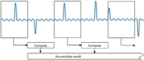
Gaps between measurements from a typical power measurement instrument provide only an average approximation of power.
(Source: Newtons4th LTD)
Furthermore, the standards specify that the UUT must be tested at the load conditions as shown in this table:
{table 1}
The UUT must be operated at 100% of nameplate output current for at least 30 minutes. After this warm-up period, if the power level does not drift by more than 5% from the maximum value observed, the UUT can be considered stable, and the measurements can be recorded. If AC input power is not stable over a five-minute period, the guidelines established by IEC 62301 for measuring average power or accumulated energy over time for both AC input and DC output are followed.
The new requirements further state that efficiency measurements shall be conducted in sequence from Load Condition 1 to Load Condition 5 as indicated in the table above. Efficiency is calculated by dividing the devices’ measured DC output power at a given load condition by the true AC input power measured at that load condition. The input power must be measured with an appropriate watt meter or power analyzer. Average efficiency is calculated as the arithmetic mean of the efficiency values calculated at Load Conditions 1, 2, 3, and 4.
It is critical to use short and properly sized test cables to reduce cable power loss as much as possible. It is also recommended to measure the output voltage right at the output connector, not after a mating connector. The standard allows cutting the output connector off, but this shouldn’t be needed if you pay attention to the connection. Significant losses can be achieved through the mating connector. For that reason, you may need to use other methods such as clamps and tight-fitting pins or wire to ensure a low loss interface with the output connector.
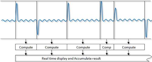
No gaps and variable windows measurement between peaks provide the true standby power.
(Source: Newtons4th LTD)
No Load Power
Equipment Considerations:
The ambient temperature should be 20C ± 5 with still air.
AC power source should not exceed 2% harmonic content, up to and including the 13th harmonic.
The crest factor should be between 1.34 and 1.49.
Measurements of power less than 0.5W should be made with an uncertainty of less than or equal to 0.01W at the 95% confidence level.
Power measurement instruments must have a resolution of 0.01W or better.
Power measurement instruments have to be capable of integrating energy over any user selected time interval with an energy resolution of less than or equal to 0.1mWh, and integrating time displayed with a resolution of 1 second or less.
READ MORE ABOUT THE DoE ON DESIGN NEWS:
Measurement Considerations:
If power consumption is stable (defined as less than 5% variation from the mean over an interval of 5 minutes), the power consumption can be read directly from the meter. If power consumption fluctuates, energy consumption should be measured over a period of time and then divided by the measurement period to determine average power.
However, the standby power can be asymmetrical and complicated further with low duty cycle current pulses. This is particularly true for high efficiency power supplies where the control scheme uses burst mode operation to lower no-load and low-load loss. So do not assume that a standby power profile is symmetrical and therefore can be accurately quantified with gaps between measurements by integration over a long period of time. Such a measurement technique may miss events and provide only an average approximation of power rather than precise true power.
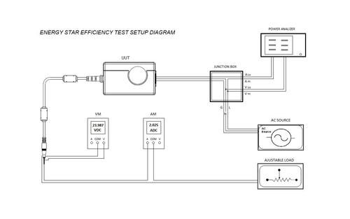
Voltmeter must sense voltage at the output side of the connector, not after the mating connector. Load connections at the output connector must make a good solid connection. Keep connections between junction box and UUT as short as possible.
The instability in power is due to the power analyzer sampling technique not the device under test. High performance power analyzers are required to achieve measurement stability and reflect the true standby power with a short measurement time.
It is a good practice to disconnect the unit under test from load when measuring no-load input power since some electronic loads may still provide a slight load even though the measurement is set to zero. Also, verify that the power analyzer is connected according to the manufacturers’ recommendations as the power analyzers may also add load to the reading if not properly connected.
In summary, the new DoE Level VI efficiency and no-load power requirements are now in effect and applicable to external power supplies manufactured or sold in the US. For that reason, care must be taken in the setup and method to achieve accurate efficiency and no-load power measurements. The use of older power meters or power analyzers may not be adequate.
Lorenzo Cividino is director, Global Application Engineering & Support, for SL Power Electronics.
You May Also Like
Editors' Choice


Jun 4 - Jun 6, 2024
Jun 4 - Jun 6, 2024
Innovation in automation starts here. Discover and collaborate on automation solutions that are revolutionizing the entire production lifecycle — from design to production to market — and sharpen your competitive edge. ATX South is part of IME South, a six-in-one expo offering the latest insights & solutions spanning medtech, packaging, automation, plastics, design, & processing.
Register Now