Can You Optimize this Example MCU-Based Design for Low Power Operation?
April 14, 2015

In preparation for my upcoming Design News Continuing Education Center online course Designing Low Power Systems using Battery and Energy Harvesting Energy Sources May 4-8, I've been rereading one of my favorite low power design application notes from Microchip. I used this application note as one of the source materials for a CEC course I did back in January 2013, Getting the Most out of Low Power MCUs. The application note (as well as my archived course) are worth a periodic visit to remind us of some of the most useful tricks and techniques we can use to reduce the power dissipation in an MCU-based design.
One of the reasons I like the application note so much is that it uses a simple example design to make a few key points. I always find design examples to be much more helpful in explaining concepts than a dry textbook approach, so I try to include them in most of my online courses. Take a look at the example design from the application note and see where you might be able to improve the design to reduce overall system power use.
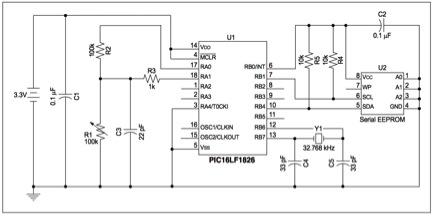
Figure 1 below shows a block diagram of the example design -- a fairly simple MCU-based sensor. The MCU, a Microchip PIC16LF1826, takes a data sample via the variable resistor R1 (on the left side of the diagram), which changes value as the temperature changes. The MCU translates the resistance, using a simple look-up table, into a standard centigrade temperature value and then stores it in the data logging serial EEPROM (shown on the right side of the diagram) once a full page of 32 readings is available. Samples are taken every 100 milliseconds and require 50 microseconds to take a reading. It takes 5 milliseconds to store the page of logged data into the serial EEPROM.

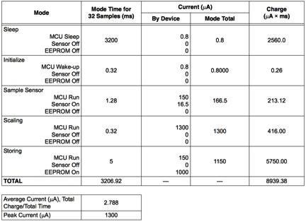
The application note describes the first step in optimizing the design. You first determine the power dissipation of the MCU during the various operating modes -- some modes run at low power since the MCU can be put into a sleep mode, between sensor readings when no CPU operations are required. You can just set a timer and interrupt the CPU to take the next sensor reading when it is time. Once you list the various operating modes you can create a power profile table, shown in Figure 2, that lists the various current expenditures of the MCU, sensor, and EEPROM in each mode. When combined with the time required in each mode you can next determine the current required. The average current is just the total charge required, 8939.38 uA x ms, divided by the time required for the periodic function measured -- in this case 3206.92 ms. Peak current can also be calculated so the power source (battery) for the sub-system can be appropriately specified.

The above technique is very helpful for optimizing the overall power expended by the MCU and the rest of the system. It is important however to look at the rest of the system to make sure you haven't overlooked some additional power savings. Too often, we focus on just the MCU and the use of low power modes and consider the job done. Take a few moments to look at Figure 1 again, and the power profile listed in Figure 2. Do you see any opportunities for further reducing the overall power use of the system? Take a minute to look closely and then you can continue to the next section for a couple ideas that can help you reduce power in your next design.
MORE FROM DESIGN NEWS: How Low Can You Go? Getting the most out of Low Power MCUs
Because the example system is fairly simple, you may have noticed the implementation for the sensor and the EEPROM and that in the power profile these devices are listed as off during the modes where they are not used. This is a perfect technique to reduce power, but the diagram in Figure 1 shows that these devices are always on. How can we change the design to allow these devices to be powered off when they are not needed?
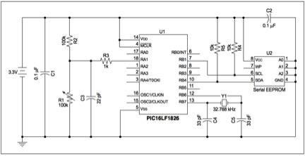
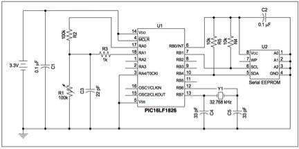
Figure 3 shows one approach to the changes needed to control the power to the sensor and the serial EEPROM. If MCU outputs are sufficient to power to the sensor and the serial EEPROM we can connect the MCU to the devices as shown in Figure 3 and just turn these outputs on and off as needed. If more power is required than the MCU can easily source, the output can be used to drive a MOSFET, which can power the circuit. In low powered designs, the MCU is a natural for controlling power of the various peripherals and modern MCUs typically have a few high power capable outputs for this reason.

This is just one example from the above application note, but a good one to illustrate a simple design technique that we may miss when we focus on just keeping the MCU operating at low power. Use the power profile to identify all the power sources in your design and then identify options for reducing power to all the devices in the design. Make sure you take into account power on and off delays and other secondary effects when you use this technique, and modify the power profile to keep track, but you should find the overall technique described in the application note a valuable addition, or reminder, to your low power design tool kit.
Warren Miller has more than 30 years of experience in electronics and has held a variety of positions in engineering, applications, strategic marketing, and product planning with large electronics companies like Advanced Micro Devices, Actel, and Avnet, as well as with a variety of smaller startups. He has in-depth experience of programmable devices (PLDs, FPGAs, MCUs, and ASICs) in industrial, networking, and consumer applications and holds several device patents.
Design engineers, New England's premier design and manufacturing event, Design & Manufacturing New England, will take place in Boston, May 6-7, 2015. A Design News event, Design & Manufacturing New England is your chance to meet qualified suppliers, get hands-on with the latest technologies, be informed, and expand your network. Learn more here.
About the Author(s)
You May Also Like


