How Does an Engineer Predict Step Motor Pull-Out Torque?
March 27, 2014

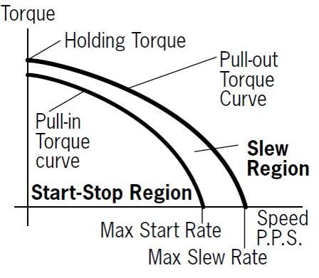
In a recent article, I wrote about step-motor system performance emphasizing key concepts that all engineers need to understand about this widely-used electro-magnetic-mechanical digital actuator. As a continuation of that discussion in this article, I talk about step-motor pull-out torque curves, as this is the most important information provided by the motor manufacturer. This curve of maximum available motor torque vs. speed (pulses per second) is an experimental curve obtained using a particular mode of operation, e.g., two-phase-on, full-step mode, and a particular driver method, e.g., voltage control or current control.

The pull-in torque curve shows the maximum friction torque with which the motor can start, at different stepping rates, without losing any steps. In an actual application, this curve has to be shifted to account for the load inertia. The pull-out torque curve shows the available torque when the motor runs at a constant speed at a given frequency. In an application, this torque is used for overcoming the load friction torque and for accelerating the load and motor inertia. The driver selected has a huge influence on the output torque and power.
The engineer will use the motor with the mode (e.g., half-step or quarter-step) and driver method dictated by the application. Can an engineer predict the pull-out torque curve for a step motor under conditions specific to the application? The answer is yes, and, as you might expect, it is done through modeling.

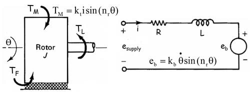
The rotational (ϴ) mechanical subsystem consists of a rotor inertia J, friction torque TF (Coulomb and viscous), and load torque TL, with the coupling to the electrical subsystem generated through the magnetic field and represented by magnetic torque, TM, proportional to phase current, i, with a proportionality constant kt. The number of rotor teeth is nr. The electrical subsystem consists of a DC voltage supply esupply, phase current, i, phase resistance, R, and phase self-inductance, L, with the coupling to the mechanical subsystem generated through the magnetic field and represented by a speed-dependent voltage eb with a proportionality constant kb. In addition, because the motor rotor has a permanent magnet, there is a detent torque, TD, occurring at four times the frequency of the magnetic torque, even in the absence of any phase current. To this must be added the driver model for either voltage control or current control.
The pull-out torque is obtained by applying a ramp load torque, TL, at a specified speed (pulses per second), running the simulation, and observing the value of the load torque at which the motor losses synchronization, i.e., starts to miss steps. This is then repeated for a range of speeds. The pull-in torque curve is obtained by applying a specified load torque and running a sequence of simulations at increasing speeds to determine the maximum speed possible for motor operation at that load torque.
While more accurate hybrid motor models exist, the model described here is most adequate for step-motor system design. Parameter identification is critical and manufacturer motor data is often sparse with large tolerances. All the parameters in this model can be determined from what is typically given in the motor data sheet. If accurate model prediction is essential, there is no substitute for measurement to validate data sheets.
Related posts:
About the Author(s)
You May Also Like


