Innovations in BLDC Motor Driver ICs
October 16, 2014

Modern brush DC electric motors have been used in the industry for almost 180 years, but they have several drawbacks. Efficiency is compromised by poor brush contact and arcing between the brushes and the rotor. The brushless DC (BLDC) motor addresses these issues by replacing the brushes with an electronic commutator. Improvements in efficiency are claimed to be of the order of 20% to 30%. BLDC motors have a small form factor, are lighter, and have longer life compared to a conventional brush DC motor.
The acceptance rate of BLDC motors has always been determined by the cost. The added cost and complexity of electronic commutation drivers has discouraged some engineers from considering a BLDC for their designs. But as this article will explain, advances in integrated BLDC drivers featuring onchip commutation considerably reduce BLDC motor control cost and development time.

Market trends
The effect of global initiatives to reduce carbon footprints can be seen in higher efficiency requirements such as Energy Star for consumer products. Refrigerator, air conditioner, fan, and other appliance manufacturers are requiring higher-efficiency BLDC motors and drives to meet these standards.
Automotive initiatives that are focused on weight reduction to improve fuel efficiency have required a switch from engine belt-driven drives to BLDC motors for electronic power steering, air conditioning, oil pump, and other applications. This trend can be seen in the data from IMS Research (LINK) that projects 480 million BLDC motors will be used in gasoline-fueled light vehicles by 2018; 53% more than in 2011.
The switch from AC-powered hand and lawn and garden tools to cordless battery-powered devices has spurred innovative BLDC motor and drive designs to reduce weight and size for improved ergonomics and increased battery life.

Technology trend
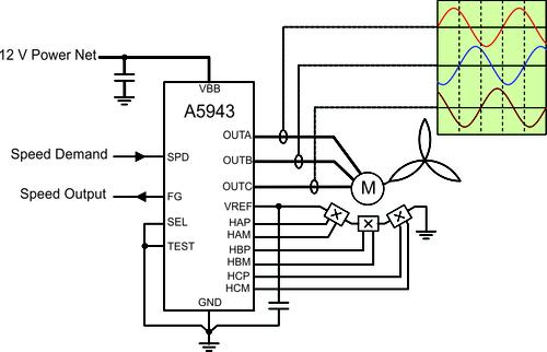
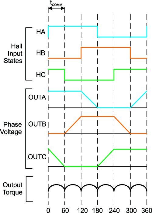
The BLDC motor's electronic commutator sequentially energizes the stator coils generating a rotating electric field that "drags" the rotor around with it. Efficient operation relies on precise energizing of the coils depending on the relative positions of stator and rotor. BLDC motors use either sensor or sensorless feedback for rotor positional feedback. In a sensor design, three Hall-effect sensor ICs are mounted in a location near the motor stator. The timing of the Hall sensor IC transitions correspond to the BEMF zero crossings as shown in Figure 1. In Sensorless technology drivers depend on the timing of the motor BEMF zero voltage crossing. Many applications are shifting to sensorless drivers because they eliminate the Hall sensor IC and associated circuitry in the motor design. BEMF is a function of velocity so at startup there is zero BEMF. Sensorless designs require complex open-loop startup algorithms in order to accelerate the motor to a speed where the BEMF can be detected. A Hall commutated driver always detects rotor position so startup is always dependable but adds significant cost to motor assembly.
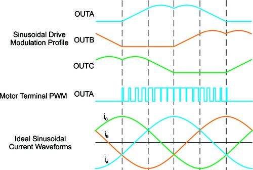
There are three control schemes for electronic commutation: trapezoidal, sinusoidal, and FOC (field-oriented control). The trapezoidal technique energizes two phases with one phase feeding current to the motor, and the other providing a current return path. The third phase is not driven. The driver controls which two of the switches in the three-phase driver must be controlled positively or negatively in order to energize the two active coils. As the motor turns, the current to the motor terminals is commutated every 60 degrees of rotation (i.e. in six steps as shown in figure 1). The advantage of the trapezoidal method is that it is the easiest to implement and the downside is that this stepped commutation causes "torque ripple." Torque ripple can cause speed changes, which can lead to vibration and audible noise.
About the Author(s)
You May Also Like


.jpg?width=300&auto=webp&quality=80&disable=upscale)


