Guide to Gliding Cable-Carrier Applications
November 18, 2011

Over the years, cable carrier manufacturers have raised the bar by designing carriers for even higher speeds, longer distances, and heavier loads. Cable carriers are an extremely low maintenance solution and can withstand extreme conditions, such as low or high temperatures, harsh weather conditions, sea water, chemical exposure, and more. Compared to cable reels or festoons, cable carriers offer a longer service life and increased system reliability.
For long-distance applications in particular, using a cable management system provides numerous benefits. Some cable carriers make travels of more than 1,300ft possible and can reach gliding speeds of 16ft per second. Cable carriers also deliver quiet operation, are capable of high acceleration, and can deliver a service life of 10 years or more. Many different types of cables and hoses can operate side by side within one cable carrier system and remain durable despite wind, weather, dirt, and chemical exposure.

The gliding principle comes into play whenever a long travel application is involved. This is because in long travels, the upper run of the cable carrier nests on the lower run. The upper run glides partially on the lower run and partially at the same height on a glide bar.
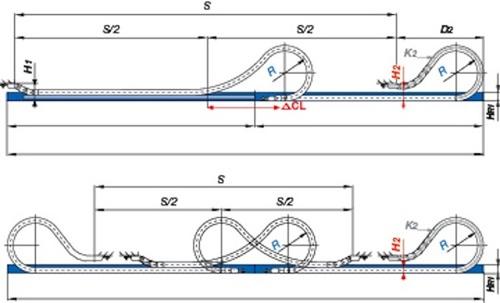
The image above shows the gliding application principle. For lateral guidance, a guide trough is necessary. If the stationary mounting bracket and the fixed end of the cables and hoses can be placed in the center, the cable carrier length is calculated as follows:
Cable carrier length: Lk = S/2 + K
S = Length of travel
R = Bending radius
HRi = Trough inner height
HF = Required clearance height
K2 = Further add-on if the mounting bracket location is set lower
K = Pi R + "safety" -- add-on for bending radius (K is taken from individual igus Series data tables)
D2 = Over length for long travels, gliding
In these examples, an Igus Energy Chain cable carrier is shown. The fixed end of the Energy Chain is located in the center of the distance to be traveled.
Guide troughs
A guide trough is an important element in long travel applications. The height of the trough must be at least twice the total chain link height, and the sides should provide a chamfered opening. When the upper run cannot glide on the lower run, glide bars must be installed along the sides of the trough.
Important tip: When assembling the trough parts, the following points must be given particular attention:
Properly align all trough parts upon installation
All screw heads should be flush with the trough
There must be a smooth leveled transition between the end of the chain and the glide bars, and
There must be a solid connection with the glide surface.
Travel speeds and accelerations
Travel speeds up to 16.4ft per sec in continuous operation are possible and exist on current applications. In special cases, even higher speeds are possible.
For example, Igus's E4/100 and E4/4 Energy Chains achieve speeds of 72ft per second and accelerations of 2,572ft per second in crash test units.
About the Author(s)
You May Also Like


