Even More on Rotary Encoders
March 5, 2013

This column wraps up our discussion of encoders with information about resolvers, which provide angular data over 360 degrees.
A resolver looks like an electric motor, with a rotor and a stator, but it acts like a rotating transformer. A sine-wave exciter signal couples to a primary coil on the rotor. As the rotor turns, the primary coil couples with two coils in the stator.
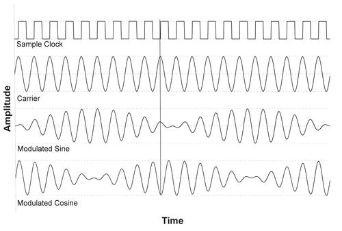
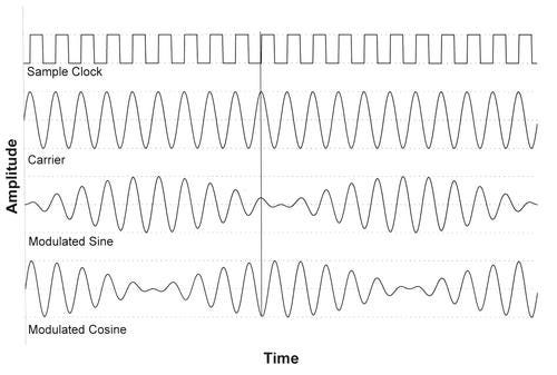
These two coils -- mounted 90 degrees apart -- pick up the excitation signal. The orthogonal positions of the secondary coils cause them to produce signals at the excitation frequency, but amplitude modulated by the sine and cosine of the rotor's angular position. (See diagram.) Many data sheets and app notes show only the demodulated sine and cosine signals rather than the actual modulated output from a resolver.

You could use two ADCs to simultaneously capture sine and cosine voltages when the excitation signal reaches its peak. At that point the sine and cosine signals reach their peak and undergo their smallest changes (dV/dt). You can use the sine and cosine values to determine the shaft's angular position. Many descriptions of resolvers include the relationship:
θ = arctan[(sin θ)/(cos θ)]
But it proves unusable. At 90 degrees , cos θ = 0, so the quotient becomes infinity. When you know the previous shaft position (a), you can use the identity to find the new position, B:
sin(a + B) = (sin a)(cos B) + (sin B)(cos a)
Suppose a resolver in equipment always starts at a=15 degrees and you have the resolver's sine and cosine values for that location. The shaft then rotates to a different position (B) and at that location, the demodulated sin(B) = 0.60, and cos(B) = 0.80:
sin(15 degrees + B) = (sin 15 degrees )(cos B) + (sin B)(cos 15 degrees )
sin(15 degrees + B) = (0.26)(cos B) + (sin B)(0.97)
sin(15 degrees + B) = (0.26)(0.80) + (0.80)(0.97)
sin(15 degrees + B) = 0.79, arcsin(0.79) = 52 degrees , and B = 37 degrees
This math technique requires the resolver interface to track the angular position and keep it up to date. The Analog Devices AD2S1210 resolver-to-digital converter, for example, uses this tracking principle within a closed-loop circuit to provide continuous output of position data. Users can choose a resolution, from 10 bits to 16 bits. At the 10-bit setting, the device can track position at a speed as high as 3,125 rps.
Given the complexity of resolver-signal conversion, why would an engineer use one? Resolvers have a high tolerance to dirt and grime and can withstand mechanical shock better than encoders. Resolvers also operate over a wider temperature range than other encoder types.
For more information:
"Dynamic Characteristics of Tracking Converters," AN-264. Analog Devices.
"TMS320F240 DSP Solution for Obtaining Resolver Angular Position and Speed," Texas Instruments.
"Encoder vs. Resolver-Based Servo Systems," Ormec.
"Synchro/Resolver Conversion Handbook," Data Device Corp. Ormec.
Related posts:
About the Author(s)
You May Also Like
.jpg?width=300&auto=webp&quality=80&disable=upscale)


