Tips and Tricks for a Successful Injection Molding Design
Part of being a supplier is coaching a customer to a successful design for the manufacturing process. Here are some pointers to help you and your parts succeed.
March 15, 2022

Gus Breiland
Getting early feedback on your CAD model can save you time and money later. Bringing in your supplier early to help review your needs against geometry limitations will prevent surprises and added delays once you are ready to order.
How thickness affects parts
|
Suppliers love seeing uniform wall thicknesses in models. It tells them that you visualized how injection molded parts cool and harden. Having uniform wall thicknesses between 0.060 and 0.120 in. (1.5 to 3.0 mm) is crucial to ensuring that parts cool evenly.
Be wary of saving too much weight or you might end up with:
cracking
suppressed cooling and possibly warp
incomplete filling or shorts
weak knit lines and fracture points
excessive or premature wear at the parting line
Overly thick walls could cause:
sink
porosity
warp
flow lines
#1 draft picks
Draft is that slight angle that helps parts pop out of molds. Adding draft early in a design helps communicate your expected parting line to the molder. Adding it into your sketch or feature tree of the model makes it part of your design and not an afterthought.
Cosmetic parts need more draft, especially when applying textures and polish. Functional parts may not need as much, but 1° should be the minimum draft for all parts, especially with aluminum tooling.
Draft and uniform wall thicknesses let parts cool within the injection mold without binding or twisting, avoiding internal stress to the part and mold. If your part “potato chips” inside the mold, the added locking force of the part binding adds stress to the ejection system. That can bend ejector pins and other components, risking damage to molds, which, in turn delays your parts. Neither party wants this.
Why radii deserve love
|
Resin hates to be forced into a sharp corner, especially as it cools and relaxes. Radii help reduce shear and turbulence caused by sharp corners and abrupt flow changes. As we think about filling a mold, we have a fluid that flows through the cavity — smooth bends make for better fill and stronger parts.
Visualize this: Your part is the positive form. The mold is the negative form split in half. So, a part’s inside corner is an outside corner on the mold. As the part cools, it shrinks. Now, that inside resin corner is pressed harder against the mold’s outside corner. If that outside corner is sharp, the mold will bite into the part and stick harder than necessary. That leads to grabbing, pinching, or binding on that sharp corner. Ejector systems must push this “bite” off, which creates stress in the mold and on the part. You end up with broken parts, possible broken molds, and poorly processed parts as the molder tries to reduce risk to the injection mold and parts.
If pass-through cores are used to eliminate expensive tooling mechanisms such as lifters, cams, and other undercut forming technology, they need radii on the corners, too. Far too often, solutions are developed to reduce cost by projecting the undercut through the part to form the pass-through core without creating corner reliefs or adding room for radii to help the part eject from the mold.
Injection and ejection
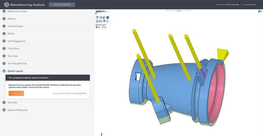
Molds require an orifice (gate) to push resin into the cavity and ejector pins to push the part off the mold. Standard single-cavity and rapid turn-time injection molding will default to the tab gate. It’s simple, effective, and doesn’t require special hardware to make it happen. Consumers are used to seeing high-volume production parts with hidden or camouflaged gating, but you can hide them with specialty gating, although it can be expensive and add time. A tab gate doesn’t require time, it just needs to be cut at the parting line and — boom! — you can start molding parts.
Ejector pins are required, but you can hide their imprints. Generally, the non-show side is inside the assembly. But you may struggle if you are making, say, a soap dish where the inside is the show side. Remember, as the part cools, it shrinks onto the mold. Molders will place “internal features” onto the ejector half of the mold even it is a show surface. Getting your molder involved early may help offer solutions to make sure your cosmetics stay pretty.
Suppliers love to see CAD files that speak to the injection molding process and that are uploaded early to get manufacturability feedback. Waiting until your design is complete to chat with your manufacturer about quality and timing may cause unwanted delays when your molder asks for changes. It could also affect other parts in your assembly right when you are ready to buy.
Want to take a deeper dive? Check out these articles devoted to wall thickness, radii, and ejector pins.
About the author
|
Gus Breiland is Senior Technical Sales Engineer at Protolabs, a digital manufacturer of custom prototypes and on-demand production parts, serving as a product development tool for engineers and a supply chain resource for companies large and small.
You May Also Like


