A Few Fundamental Facts About Micro Molding 43723
Donna Bibber of Isometric Micro Molding shares insights about the complexities of the micro-molding process, from material selection and tooling design to assembly.
August 5, 2021

Back when I was editing trade publications covering medical manufacturing, minimally invasive surgery was a hot topic, and I remember contract manufacturers telling me that the one question customers kept asking was, “How small can you make it?” Micro molding was around back then, but it was still a fairly niche industry. As medical devices continued to get smaller — not to mention shrinking electronics, telecommunication products, and automotive parts — micro molding got bigger. According to a recent report from Research and Markets, the global micro-molding market is expected to grow from $904 million in 2020 to $1.6 billion by 2025, at a compound annual growth rate (CAGR) of 11.8%. That may be a conservative estimate to my mind.
As micro molders and their customers will tell you, micro molding is not simply applying injection molding processes to the production of very small parts, implying that not much changes other than the size of the molded product. Moving from the macro to the micro level involves numerous considerations, including material sourcing, design elements, potential part assembly, and much more. We spoke with Donna Bibber, Vice President of Business Development at Isometric Micro Molding about the complexities of the process. She graciously shared her insights with PlasticsToday.
Bibber will present case studies in micro molding and the automated assembly of miniaturized devices at the co-located Medical Design & Manufacturing (MD&M) West and Plastec West event, which runs in Anaheim, CA, on Aug. 10 to 12, 2021. Her presentation in the Tech Theater (booth 1175) is scheduled for Aug. 10 at 2:30 PM.
First things first, what part dimensions are we talking about when we reference micro molding? Is there a standard definition?
Donna Bibber: There is an unspoken industry standard definition of micromolding and it encompasses the following:
Parts that are fractions of a plastic pellet;
parts that weigh fractions of a gram;
parts with a wall thickness ranging from 0.005 to 0.015 in. (125 to 375 microns);
parts or sub-assemblies requiring single-micron tolerances, or stack-up tolerances that lead to single-micron tolerances;
high length-to-thickness (L:T) ratios or length-to-diameter (L:D) aspect ratios;
larger parts up to 6 in. long that have microscopic features or single-micron tolerances.
My understanding is that design for manufacturing (DfM) is critically important in micro molding. How is it different from DfM for conventional molding?
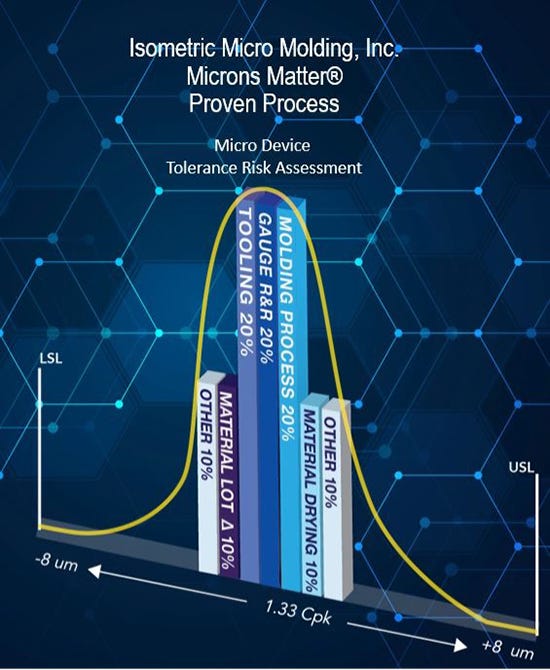
Bibber: At Isometric Micro Molding, our approach to DfM/DfA is called Microns Matter, which encompasses a very precise and detailed process map of all sub-processes to address all critical attributes of the product and assembly. These sub-processes typically include mold design/build; injection molding process variables; gage R&R; material lot-to-lot variation; and material moisture percentage range.
While each process map varies, it is important to address the tolerance percentage error in each process step. For example, building the mold to 20% of tolerance, leaves 80% to the other noted variables.
|
The DfM/DfA process at Isometric Micro Molding is called Microns Matter, which encompasses a detailed map of all sub-processes to address all critical attributes of the product and assembly. |
In many ways, it’s a process failure mode effects analysis (PFMEA ) and control plan on steroids. Even at the quoting stage, this process details the solution that is being quoted as an initial risk assessment by our technical and experienced plastics engineering staff. This way, we devise a project solution that has already been vetted to ensure success.
The conventional DfM process isn’t typically designed to address stack-up tolerances of single microns but more geared to plus or minus a few thousandths of an inch. Micro-molded parts typically have tighter tolerances, thinner wall thicknesses, are challenging to handle and package, and, therefore, require a more stringent review of all process inputs and the planned percentage of tolerance they will encompass.
|
Donna Bibber, Vice President of Business Development, Isometric Micro Molding. |
The last time we spoke, you stressed the importance of tooling design in micro molding. What are the complexities and challenges involved in that?
Bibber: Mold design and mold fabrication are the enabling factors in micro-molding success. Isometric has seven full-time mold designers on staff. The mold designer’s experience, in a vertically integrated company, is key to mold-making success. Isometric’s mold designers have a clear understanding of what is possible to micro machine for molds with part features that are a fraction of the diameter of a human hair. They need to know what cutter size and depth is possible, over burn in EDM, and whether wire EDM or milling will be best to achieve the desired feature and surface finish. It’s virtually impossible to outsource this skill set along with those needed for mold making. Discussions regarding datum structure, from designing the mold to programming the CT scanner and automation, start with a solid mold design and plan to achieve single-micron-tolerance components and assemblies.
What about material selection? Materials behave differently when they are used in micro-molding applications, correct?
Bibber: Materials do behave differently in micro molding, and the reason is partially because of the instantaneous polymer shear that tiny mold gate diameters present. It is not uncommon for micro molded parts to require 40,000 to 50,000 psi of injection pressure to fill, and the speed to fill them is a mere 0.01 seconds. The instantaneous but seemingly important shear rate helps fill high aspect ratio parts if the flow is balanced properly.
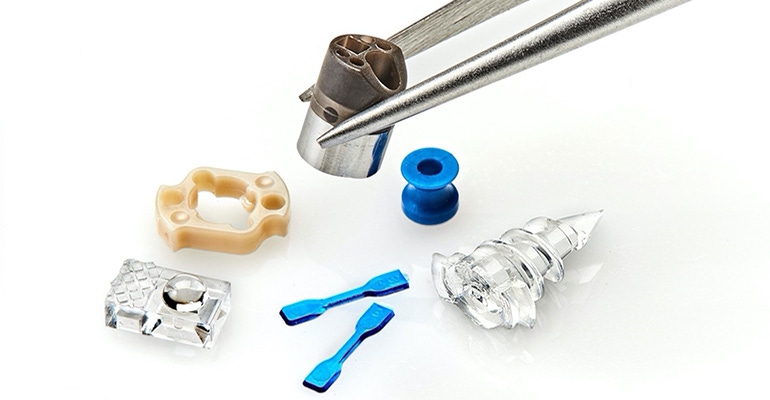
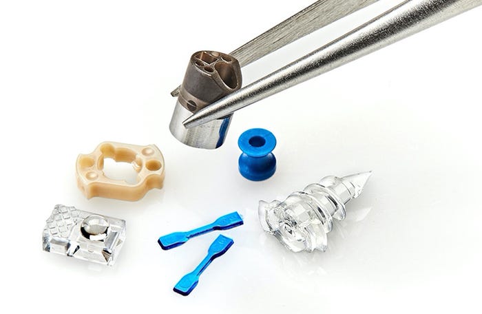
I will send you an image [published below] that shows Isometric’s tensile bars, which are the size of the letter I on a keyboard. The gating, shear effects, and 0.001 to 0.008-in.-thick tensile bar samples allow Isometric to mitigate risks within two to three days by molding these tensile bars and extrapolating the injection molding parameters necessary for production molds. These tensile bars also simulate gate diameters and styles of gates that will be used in production.
|
Isometric Micro Molding's tensile bars, medical implants, and other molded parts. |
Design engineers might unknowingly limit their ability to design small to micro-sized parts because they believe they are too thin, too small with not enough “real estate,” or too flimsy or weak to function. Oftentimes, material-grade selection knowledge is limited, or outdated even, and can lead to late-phase project failures. These failures can be prevented early and also strengthen regulatory submissions with micro tensile bar empirical data to support finite element analysis (FEA) theoretical data.
Given the dimensions you are working with, assembly must be a real headache. How do you deal with that?
Bibber: Referring back to Isometric’s Microns Matter process, the consolidation of parts and stack-up tolerances are measured best using CT scanning, starting as early as the design of experiment (DOE) process. DOE is a tool that compares molding process variables to the measurement of parts and statistically analyzes the process variables that have the most influence on critical to function attributes.
For example, Isometric’s in-house CT scanning technology was used to scan 16-cavity molded parts [as shown in the image below] and allow the CT scanning software to overlay the part scan over the perfect CAD file, resulting in color deviation plots reflecting a full first-article inspection. This analysis occurs in 15 minutes and is fed immediately back to the process engineers who use the information to dial in the process. In 15 minutes, the effects of critical to function dimensions with the 11 DOE processes are depicted visually, allowing the process to be quickly and accurately dialed in reliably with Cpk > 1.33.
|
In-house scanning technology is used by Isometric Micro Molding to capture cavity-to-cavity variation. |
All sixteen parts are then overlayed over one another and over the perfect model to capture cavity-to-cavity variation. This variation can then be extrapolated to an estimated overall part variation in the future planned 32-cavity mold; 16 cavities of part 1, 16 cavities of part 2, and stack-up tolerances of the assemblies are also CT scanned, showing full extremes of combination assemblies and will reflect real stack-up tolerances in a future automated assembly.
The 15-minute CT scan in this example showed 3-micron color deviations from scanning all 16 cavities at once. It showed that cavities 6 and 7 had some mold filling issues near their base. Quick analysis allows process engineers to troubleshoot and hone in on this fill difference, process it out, and quickly move on to the next troubleshooting steps, such as adding mold vents to eliminate trapped gas causing non-fills.
Can you share some details about a recent project that was particularly challenging?
Bibber: Let me bring in Brent Hahn, Director of Sales and Marketing, to answer that question.
Brent Hahn: Isometric Micro Molding recently supported a medical device company with a project that had 38 features that were 0.008-in.-thick with a flow length of 0.900 in. (112.5:1 Ratio) and molded in PEEK. By working together with the customer’s design team, Isometric was able to create a solution that successfully incorporated design elements that Isometric needed and kept the customer’s design intent and functionality. This collaborative approach and open communication created a fast and successful outcome.
To wrap up, What do you see as the next frontier of miniaturization?
Bibber: The future is extremely promising for miniaturization due to the demand in key market segments such as cardiology, neurology, ophthalmology, glucose monitoring, ENT, fiber optics, and other high-precision markets.
Many small to tiny assemblies will require artificial intelligence built into the manufacturing process, as well as the devices, allowing the data to be used for developing even smaller and smarter devices in the future.
Other areas of opportunity for miniaturization include specialty surfaces developed via biomimicry, where nature is used to mimic hydrophobicity and hydrophilicity, to name just a couple of properties. These surfaces will enable new devices in the body that will prevent fluids from going in specific locations and attract fluids to other locations within the same device.
These are exciting and fruitful times for micro molders and automated assembly integration companies like Isometric Micro Molding that have invested many years in developing skill sets to address these market needs.
About the Author(s)
You May Also Like


.jpg?width=300&auto=webp&quality=80&disable=upscale)

