Switched-Capacitor Filters: An Introduction
June 11, 2013

In my May blog post, I described the construction of a low-pass filter that used op-amps, capacitors, and resistors. I ignored thermal drift, long-term accuracy, and other characteristics and tested only frequency response.
Passive components can become troublesome, though, because small changes in values alter a filter's cutoff frequency. More importantly, small changes can affect the poles and zeros of a filter's transfer function and introduce ripple, which has a greater effect on a filter's performance.1

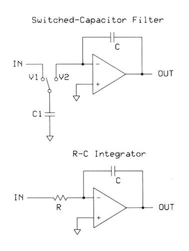
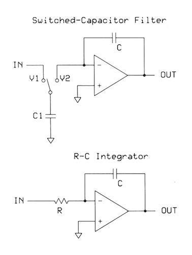
Switched-capacitor filters (SCFs) offer good alternatives. In a SCF, capacitors and switches take the place of resistors and accurately reproduce the characteristics of continuous-time Bessel, Butterworth, and elliptical filters. However, instead of relying on specific component values, an SCF takes advantage of the ratio of two capacitances, shown at the top of the figure. Capacitor C1 transfers charge from the input signal (V1) to the op-amp's inverting input (V2).
You probably remember the equation C = q/V or q = C∙V, where q equals charge. Connecting C1 to V1 transfers charge to the capacitor. Connecting C1 to V2 transfers charge to the op-amp input. (Charge also can transfer from V2 to V1.) Thus the change in charge amounts to
∆q = C1(V1 - V2)
Capacitor switching occurs rapidly, so, for n switch actions over a given time, ∆t:
∆q/∆t = C1(V1 - V2)n/∆t
Because ∆q/∆t = I, and n/∆t = fclk:
I = C1(V1 - V2)fclk
Then, using Ohm's Law, R = E/I, and an algebraic rearrangement:
(V1 - V2)/ I = 1/C1∙fclk = R
For the simple R-C integrator circuit (also shown in the figure), the cutoff frequency, fc = 1/2πRC. Substitute 1/C1∙fclk for resistance R:
fc = C1∙fclk/2πC
So, for an SCF, the frequency response depends solely on the ratio of two capacitors, C and C1, and the switching-clock frequency, fclk. To adjust the filter cutoff frequency (fc), you may change the capacitor ratio, the switching frequency, or both.
Because semiconductor manufacturers can create precise capacitances on a die, SCFs can achieve an fc accuracy impossible with a discrete-component filter. In commercial SCFs, the fc depends solely on fclk. The Maxim Integrated MAX7490 dual biquad SCF, for example, has a corner-frequency accuracy as good as 0.2 percent and a temperature drift of only 10 ppm/ degrees C. (A biquad filter has several feedback paths.)
There will more about SCF characteristics and uses in the July column.
Reference:
Hashemi, Kevan, "Filter Design Guide," Brandeis University, 2013.
For more information:
Markell, Richard, "Take the Mystery Out of the Switched-Capacitor Filter," AN40, Linear Technology, 1990.
Related posts:
About the Author(s)
You May Also Like
.jpg?width=300&auto=webp&quality=80&disable=upscale)


