Switched-Capacitor Filter Tests
July 1, 2013

My previous column introduced switched-capacitor filters (SCFs) and explained how the capacitors can replace resistors and improve filter accuracy. To find out more about how well SCFs behave, I used a Linear Technology LTC1164-7 low-power, linear-phase 8th-order low-pass filter. According to the data sheet, this SCF exhibits a steeper roll-off, or attenuation, than an 8th-order Bessel filter. Keep in mind a filter name, such as Bessel or Butterworth, refers to the filter's characteristics, not to a specific circuit class.
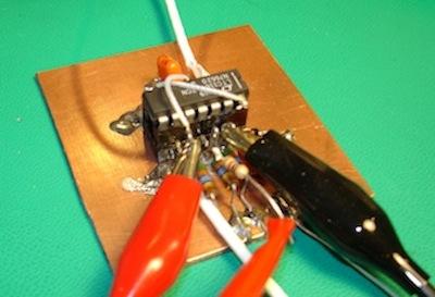
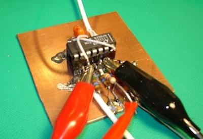
To test the LTC1164-7 I created a breadboard in the style of Jim Williams and Bob Pease -- a piece of copper-clad PCB material that serves as a ground plane for connections. A solderless breadboard just won't do for a sensitive analog circuit. I used short wires for pin-to-pin connections along with 51-Mohm resistors used as standoffs.

Lab equipment comprised a Wavetek 148A signal generator, an HP3478A digital multimeter for AC RMS measurements, and a Fluke 1953A counter/timer. A Tek FG-5010 function generator provided the SCF clock signal. I wired the IC for a 50:1 clock-to-cutoff-frequency ratio, so I needed a 75-kHz clock for a 1500-Hz fc. The LTC1164-7 required a plus or minus 5V power supply. I used a Tektronix TDS 460A scope to monitor signals.
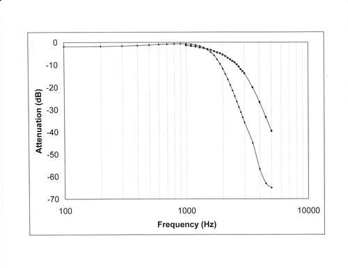
The graph above shows the measured results for a 3.00V sine wave (2.12 Vrms). The longer plot shows my measurements and the shorter plot comes from data calculated with filter-design software for an 8th-order Bessel filter. The LTC1164-7 slightly attenuates signals below the cutoff frequency. The LTC1164-7 data sheet specifies a -38 to -30dB attenuation at twice the fc value, which agreed with my -35.7dB measurement at 3,000Hz.

Because an SCF uses capacitors to sample signals, it might require an anti-alias filter on its input. But an SCF oversamples the analog input, so a simple R-C circuit will work well. A look at the filter output shows a stepped sine wave that looks like what you would expect from a digital-to-analog converter. If you use an SCF with an ADC, ensure you carefully synchronize the ADC and SCF clocks -- or use a single clock -- to ensure the ADC received a signal that has properly settled.
Switched-capacitor filters have a few disadvantages. They exhibit greater sensitivity to noise than their op-amp-based filter siblings, and they have low-amplitude clock-signal artifacts -- clock feedthrough -- on their outputs. Because an SCF uses a clock signal far above its fc, a simple R-C filter on the output will attenuate clock feedthrough. SCFs, like all precision analog circuits, require careful attention to PCB layout, signal routing, and grounding.
For more information:
Markell, Richard, "Take the Mystery out of the Switched-Capacitor Filter: The System Designer's Filter Compendium," AN-40, Linear Technology.
"The Basics of Anti-Aliasing: Using Switched-Capacitor Filters," Tutorial 3494. Maxim Integrated.
Related posts:
About the Author(s)
You May Also Like
.jpg?width=300&auto=webp&quality=80&disable=upscale)


