Specifying & Creating Data-Acquisition Systems, Part 3
April 5, 2012

Voltages from items such as batteries, photovoltaic panels, and temperature sensors vary slightly and slowly over time, and for them, an added noise filter serves no purpose. On the other hand, signals that include unwanted components at frequencies above those you want to measure require a low-pass anti-alias filter to prevent unwanted high-frequency signals from "folding," or aliasing, into your samples. The Nyquist-Shannon sampling theorem explains how and where such aliasing occurs based on a given sampling frequency.
Before you can choose such a filter, you must know the upper frequency (fc) of the signals you want to measure. Let's set the fc value at 1,500Hz. You also must know the dynamic range of your analog-to-digital converter (ADC). Assume you have a 14-bit ADC, which provides a dynamic range of one part in 16,384, or about 84dB. That means the ADC will produce a result for any signal within that range, based on the full-scale input of the ADC.

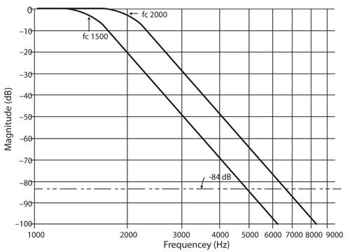
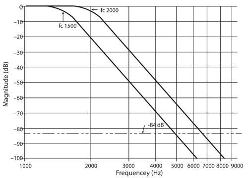
An ideal anti-alias filter would completely remove all signals above the fc value -- 1,500Hz, in this case. But real filters attenuate signals at defined rates that vary by filter type. A two-pole low-pass Butterworth filter, for example, slowly attenuates frequencies and only reaches -84dB at 19kHz, so the ADC data would include many unwanted frequency components. An eight-pole Butterworth filter reaches -84dB at about 5kHz. So you would see less data from the ADC for higher-frequency components.
Filter specifications place the fc value at the -3dB point on a filter's frequency versus attenuation curve, so needed signals at 1,500Hz would experience about a 30 percent reduction in amplitude. To avoid this unwanted attenuation, increase the fc value for the filter so signals at 1,500Hz have no attenuation. For the eight-pole Butterworth filter, an fc of 2,000Hz increases the frequency at -84dB to 6,700Hz. So the ADC can now measure signals up to this frequency.
What sample rate should you use for the ADC? The Nyquist-Shannon theorem explains the need to sample faster than twice the highest frequency. In this example, that component corresponds to the -84dB point on the filter response curve, or 6,700Hz, so you might think sampling at, say, slightly above 13.4ksamples/sec would do the job. But most measurement experts recommend from five to 10 times this upper frequency, so sampling from 33.5 to 67ksamples/sec provides better results. That means you sample at a rate from about 22 to 44 times higher than the 1,500kHz limit on your signals of interest.
If you would like to experiment with filter attenuation plots, schematic diagrams, and SPICE models, I recommend the free FilterLab software from Microchip Technology.
Related posts:
About the Author(s)
You May Also Like


