Specifying & Creating Data-Acquisition Systems, Part 1
February 29, 2012

Over the years, engineers starting their careers have asked me how to specify and create a data-acquisition system. The path can seem rocky until they analyze what they must measure and what they want to do with the measurement information. This and following columns outline how to think about such projects, for which I assume one or more "unknown" voltage signals.
You must know what to measure when you start a project. Although data-acquisition equipment can adapt to many needs, I recommend designing or configuring what you need to solve a specific problem. After solving that problem you can decide whether to add other capabilities.

Must you measure analog, digital, or both signal types? At first, analog signals seem straightforward because most of the time you will just digitize them. Digital signals could involve counting pulses or timing periods between signal transitions. And because digital signals do not always make a clean transition between logic states, you might need to treat them as analog signals, and sample them accordingly. The sampled information lets you observe analog-like behavior such as jitter, glitches, noise, and runt pulses not seen if you capture only logic-level transitions. Also, by sampling and analyzing digital signals you can determine how well they meet signal-integrity specs.
The need to sample a signal leads to the next specifications: resolution and accuracy. Manufacturers' data sheets provide this information, so get your calculator ready. For a 1V signal, a 16-bit analog-to-digital converter (ADC), for example, provides a resolution of 15.3µV, the value of its least-significant bit. A 5.50-digit DVM offers a 10µV resolution, the value of its least-significant digit. The DVM data sheet notes an accuracy of 0.012 percent, or 120V for the 1V signal. Electrical noise created within the 16-bit ADC and surrounding circuits will limit accuracy to about 14 bits, or 61µV. Match accuracy to the measurement requirements for your data. There is no need to specify accuracy in tens of microvolts when tens of millivolts will suffice. Accuracy is almost always less than a specified resolution.
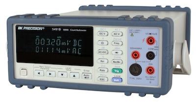
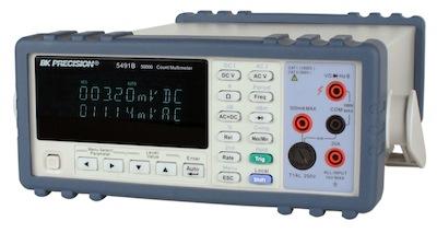
Next, consider the frequency of your signals. To test slowly changing DC or near-DC signals in, say, battery or photovoltaic-cell tests, a digital voltmeter (DVM) with a USB interface to a PC might suffice. DVMs can provide root-mean-square (rms) measurements and can average a signal over a set period, too.
When you sample AC signals, things get more complicated because you must determine the bandwidth over which you need to capture signals and then determine the appropriate sampling frequency.
Be sure to check back in with Design News next week for Specifying & Creating Data-Acquisition Systems, Part 2.
Related posts:
About the Author(s)
You May Also Like


