How to Create a Low-Pass Filter
May 7, 2013

My previous column described the Sallen-Key circuit for a low-pass filter. At times, you will not find a low-pass filter with the specifications you need in an anti-alias circuit, so you might decide to design your own.
"Can I get the same performance I see in application notes?" you might wonder. To find out, I used the free Microchip Technology FilterLab software to create a low-pass Butterworth filter based on a 1500Hz cutoff frequency, fc. For a signal at that frequency, my filter should show a -3dB attenuation.
The FilterLab software let me enter the fc value and select the filter order. I chose seventh order. As you change this value or the cutoff frequency, the graph of frequency vs. amplitude and frequency vs. phase angle change immediately so you can see the results. You also see a SPICE model and a schematic diagram of a corresponding filter circuit (see designnews.com for the circuit). I purchased the needed passive components and Microchip MCP662 dual-op amp ICs.

Rather than create a circuit-board prototype, I connected the components in a solderless breadboard. The MCP662 single-supply op amps came in SMT packages, so I used a Schmartboard 20-SOIC adapter that routed op-amp signals to pins on 0.1-inch centers.
My lab equipment was comprised of a Wavetek 148A signal generator, an HP3478A digital multimeter for AC RMS measurements, and a Fluke 1953A counter/timer. I used 6 volts to power the filter circuit and offset the test signal by three volts. The signal generator provided a filter-input signal of about 1.7 Vrms.

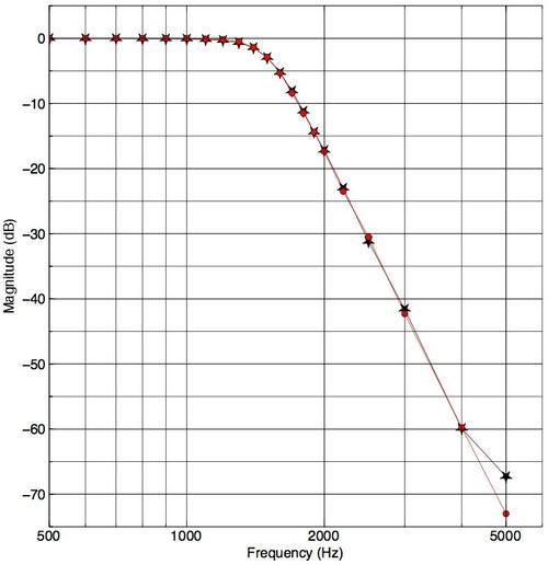
I entered in a spreadsheet the theoretical values from the FilterLab graph. A cursor gives the attenuation and frequency at any point on the graph. Next, I made several lab runs and the graph above shows the results from one. I was surprised the measurements came so close to the values predicted by the FilterLab tool. I thought my breadboard circuit might pick up noise so attenuation would not go as low as it did.
So yes, you can create your own filters, although I recommend creating a PCB with a good ground plane and shielding to protect the circuit from EMI and RFI. Ensure you use a well-filtered DC power supply, too.
The next column will examine switched-capacitor filters and their performance.
For More Information:
Download the free Microchip Technology FilterLab software, and search for FilterLab. You can download a user manual, too.
"A Beginner's Guide to Filter Topologies," Maxim Integrated.
For a multiple-feedback low-pass-filter calculator, visit Okawa Electric Design.
"Multiple Feedback Filters," MT220, Analog Devices.
Horowitz, Paul and Winfield Hill, "The Art of Electronics," 2nd ed., Chapter 5. Cambridge University Press. 1989.
Related posts:
About the Author(s)
You May Also Like
.jpg?width=300&auto=webp&quality=80&disable=upscale)


