Controlled Landing and Ascent
February 24, 2015

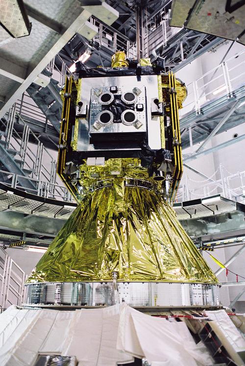
A series of electromechanical actuators and propulsion components for a 510-kg spacecraft called Hayabusa, which Moog helped Nippon Electric Company (NEC) develop in 2001, had a mission to chase down a 630-meter-long asteroid named 25143 Itokawa. The goal was to fire a small pyrotechnic charge, sending a bullet into the surface of the asteroid and scatter fragments for collection and return to Earth.
The Japan Aerospace Exploration Agency (JAXA) launched Hayabusa in 2003. After reaching Itokawa on September 12, 2005 and gathering some small samples, Hayabusa returned to Earth.
Moog's specific contribution to the mission consisted of manufacturing:
servo valves for a set of four Ion thrusters made by Mitsubishi Heavy Industries (MHI)
a filter wheel assembly
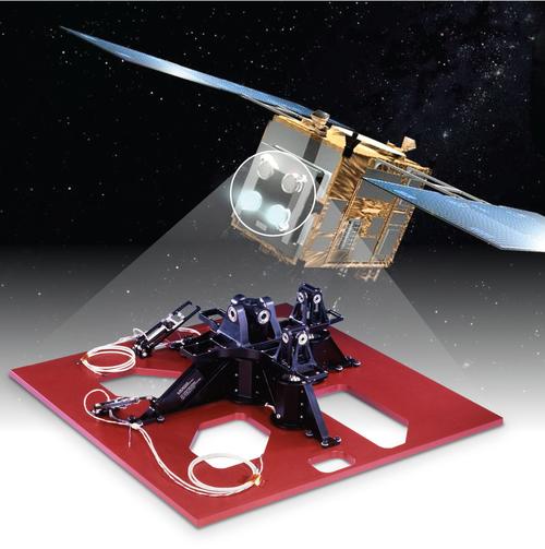
a gimballing mechanism
Hayabusa's thrusters (each measuring 15 cm in diameter by 15 cm in length) were electric propulsion technology, which was a relatively new concept at the time. It is now a more popular method of generating propulsion thrust for space applications.

It's assumed that JAXA opted for electric propulsion technology at the time to keep the spacecraft's propulsion system lightweight. The spacecraft's four ion thrusters used xenon, which is chemically inert and colorless, as a propellant - and high-performance valves injected the propellant into the thruster chamber. With ion engines, electrons ionize the propellant and an electrode system generates different polarities inside the chamber. Ultimately, the thruster discharges thousands of ion jets, creating thrust force. On its trip to and from Itokawa, Hayabusa's engines achieved a change in velocity of 1,400 m/s, consuming a total of 40 kg of xenon propellant for the mission. The engines had a nominal thrust of 8 mN.
A filter wheel assembly assisted Hayabusa's imager in collecting a picture of Itokawa's surface. Basically, the filter wheel obtains images at specific wavelengths, which scientists can combine electronically on Earth to make color images.
The gimballing mechanism system, which controlled the thrust-vector maneuvering of Hayabusa's ion thrusters, weighed approximately 3.5 kg and had a maximum power consumption of 5W.
By way of background, gimbals give design engineers flexibility. With gimbals, it's possible to orient satellite antennae or thrusters independently of their surrounding environment. Without a gimbal, a rocket engine or thruster could provide thrust in only one direction. To enable Hayabusa, or any spacecraft, to align itself with an asteroid, the gimbals give the spacecraft's thrusters the ability to tilt and initiate thrust in different directions. This became an even more critical application when Hayabusa lost attitude control after exploring Itokawa, as discussed later.
MORE FROM DESIGN NEWS: NASA's Asteroid Redirect Mission: Innovative or a Waste of Time?
A challenging aspect of the mission was the gimballing mechanism, which is somewhat like the steering system on a car. The total mass of the gimballing mechanism, four ion engines, and dry propellant tank was to equal less than 60 kg. The thrusters were a significantly larger mass than the allocated mass for the thruster gimbal. For the gimballing mechanism to support this amount of mass, designers had to scrutinize every element of its design, including materials, construction, and assembly. JAXA was optimizing the entire mass of the spacecraft - which when fully fueled equaled 510 kg - to ensure the craft would reach its target and return within the allotted propellant amounts.
As the engineers began constructing the gimbal mechanism, they agreed it was critical to design and build the gimbals and supporting structure with either aluminum or titanium, both lightweight metals commonly used on space missions. With the material discussion settled, the focus became the design. The entire gimbal structure took the form of a cross-shaped protrusion about 15 cm above the mounting platform. A cross would offer strength and stability and disperse the assembly equally between the four ion engines. The span of the cross was approximately 61 cm x 61 cm.
As work progressed, the engineers developed a number of modular sections to bolt on and secure to the mounting platform. The modular nature of these sections would enable them to be used in other ways for future missions. To achieve greater strength, the gimbal mounting platform was machined from one piece of aluminum.
About the Author(s)
You May Also Like


