Circuits Without Wires
February 1, 2012

In his influential 1959 lecture "The Two Cultures," the scientist C.P. Snow remarked that not knowing the second law of thermodynamics is equivalent to never having read a work by Shakespeare. It seems that, within the engineering community, there are also two cultures, and the situation is worsening. At one extreme, there is the trial-and-error, plug-and-chug world of just getting an answer -- the approach perpetuated by our present-day educational system. Then there is the world of understanding through modeling and the application of the laws of nature through their language, mathematics. In mechatronics, Maxwell's equations come to mind in this digital age.
The mathematical statements of Maxwell's equations are most formidable specifying the divergence and curl of electric E and magnetic B vector fields. They include the laws of Gauss, Ampere, and Faraday. Maxwell's four equations simply say that: E diverges outward from plus charges and inward to minus charges; E curls around changing B fields; B never diverges, it always loops around; and B curls around currents and changing E fields.
An excellent example of how analogies lead to understanding and the solution of real-world engineering problems is magnetic circuit analysis, which represents algebraic approximations to exact field-theory solutions. The wires of the electrical circuit are now the iron and air of the magnetic circuit. In all electromechanical devices, mechanical motion must occur, which results in changing flux linkages. In a linear electromagnetic system, inductances are functions of mechanical motion.

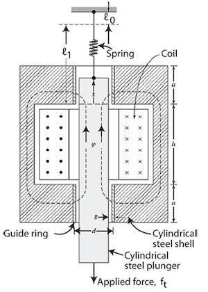
As an example, let's derive the dynamic equations of motion for an electromechanical system. The figure above shows in cross-section a cylindrical solenoid magnet in which the cylindrical plunger of mass M moves vertically in brass guide rings of thickness g and mean diameter d. The permeability of brass is the same as that of free space. The plunger is supported by a spring whose spring constant is K. Its unstretched length is ℓ0.
A mechanical load force ft is applied to the plunger from the mechanical system connected to it. Assume that the frictional force is linearly proportional to the velocity, and that the damping coefficient is B. The coil has N turns and resistance R. Its terminal voltage is et, and its current is i. The effects of magnetic leakage and reluctance of the steel are negligible. The reluctance of the magnetic circuit is that of the two guide rings in series, with the flux directed radially through them. Assume constant flux density in the guide rings with respect to the radial distance, since g (the length of the flux path in the direction of the field) << d. πxd and πad are the upper and lower areas, respectively, of the flux path perpendicular to the field. Assume that, for the upper gap reluctance expression, the field is concentrated in the area between the upper end of the plunger and the lower end of the upper guide ring. As the electrical resistance of a wire ℓ/A, the reluctances of the upper and lower gaps are g/μ0πxd and g/μ0πad, respectively, which add together to give the total reluctance. The inductance L(x) is equal to N2 divided by the total reluctance, and the magnetic force acting upward on the plunger is given by .50 i2(dL/dx). The induced voltage in the coil is given by d(Li)/dt. Application of Newton's second law and Kirchhoff's voltage law results in two dynamic equations of motion, shown below.

Related posts:
About the Author(s)
You May Also Like


