Angular Velocity: Misunderstood & Misstated
March 21, 2013

Ask any engineer what the velocity of a point on a rigid body is, and they will correctly say that it's the time rate of change of a linear position vector. Ask any engineer what angular velocity is, and they most likely will incorrectly say that it's the time rate of change of an angular position vector. And in both cases, there is usually no mention of the reference frames involved.
The misunderstanding of angular velocity, and the ambiguity that imprecise notation creates, can lead to errors resulting in lost time and money, and even tragic results.
A reference frame is a perspective from which observations are made regarding the motion of a system. A moving body, such as an automobile or airplane, frequently provides a useful reference frame for our observations of motion. Even when we are not moving, it is often easier to describe the motion of a point by reference to a moving object.
This is the case for many common machines, such as robots. An engineer needs to be able to correlate observations of position, velocity, and acceleration of points on moving bodies, as well as the angular velocities and angular accelerations of those moving bodies, from both fixed and moving reference frames.


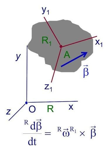
In Figure 1, R is the ground reference frame with coordinate axes xyz fixed in R. The R1 reference frame is a rigid body moving in reference frame R with coordinate axes x1y1,z1, fixed in R1. β is any vector fixed in R1. The defining equation for angular velocity ω is shown.
Angular velocity is the time rate of change of orientation of the body; it is not, in general, equal to the derivative of any single vector. However, when a rigid body R1 moves in a reference frame R in such a way that there exists throughout some time interval a unit vector whose orientation in both R1 and R is independent of the time, then rigid body R1 is said to have simple angular velocity in R throughout this time interval, and the magnitude of this angular velocity vector is the time derivative of an angle.
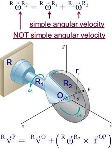
Figure 2 shows a two degree-of-freedom mechanism. R1 has simple angular velocity in R (ω1) and R2 has simple angular velocity in R1 (ω2). The Addition Theorem for Angular Velocity, i.e.

allows us to easily determine the angular velocity of R2 in R, which is not a simple angular velocity.

This theorem is very powerful as it allows one to develop an expression for a complicated angular velocity by using intermediate reference frames, real or fictitious, that have simple-angular-velocity relations between each of them. Note that there is no similar addition theorem for angular accelerations.
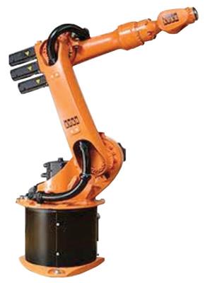
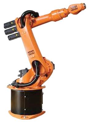
Figure 3 shows a serial robot, i.e., a series of links connected by motor-actuated joints that extend from a base to an end effector.
Each link has a simple-angular-velocity relationship with the preceding link. This makes the determination of the angular velocity of any link with respect to any other link very easy.
Related posts:
About the Author(s)
You May Also Like


