Sign up for the Design News Daily newsletter.
Who'd Thunk It? Arduino and PLCs Hook Up Via RS232 and Modbus
There is a thriving online developer community using RS232, Arduinos, and PLCs to build industrial and home automation systems on the familiar serial communication protocol Modbus.
March 3, 2016
4 Min Read
.svg?width=850&auto=webp&quality=95&format=jpg&disable=upscale "Who'd Thunk It? Arduino and PLCs Hook Up Via RS232 and Modbus")
In researching industrial controls projects for my “Introduction to PLCs” and “Advanced Programmable Logic Controllers” courses that I teach at a local Alabama community college, I was quite surprised to see that an old serial communications standard is thriving well in the manufacturing sector. The RS232 was the de facto serial communications standard used to connect printers, consumer electronics, embedded development boards, and test instrumentation to desktop PCs and notebook computers. This standard has now been replaced with the plug-play efficiency of USB.
Manufacturers have resurrected RS232 on the plant floor to network PLCs for industrial machine applications. Also, there is a thriving online developer community where engineers and makers are using RS232 and Arduinos along with PLCs to build industrial and home automation systems. A key component to this is the familiar serial communication protocol Modbus.
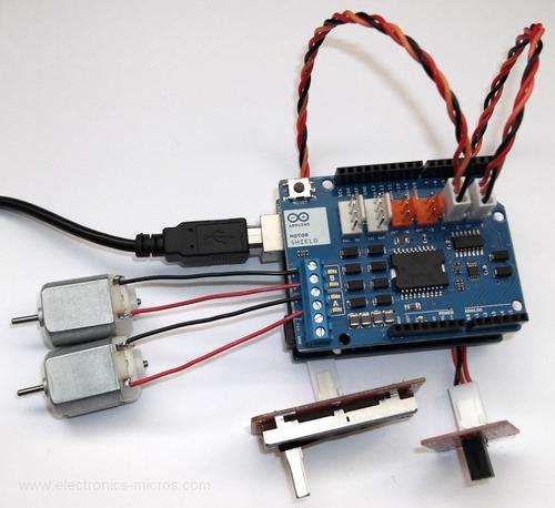
Figure 1. Arduinos are capable of reading digital and analog data as well as control DC motors using motor shields. PLCs will extend the Arduino’s reach in industrial applications.
(Source: Seeed Studio)
Originally developed for master/slave networks for industrial machine controls, Modbus is being used to connect an Arduino to a PLC. Modicon, the brand behind Modbus, introduced it to the manufacturing sector in 1979.
Modbus provides a communication method for transmitting information between two electronic controllers over data serial lines. What has made Modbus appealing to manufacturers is that it’s a free and open communication protocol. Manufacturers can easily integrate this protocol into their equipment without having to pay royalties.
With Modbus being a free and open communication protocol, makers have been using it to easily wire Arduinos and supporting shields to PLCs.
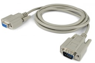
Figure 2. The RS232 or DB9 serial cable, no stranger to manufacturers using the Modbus protocol to communicate between PLCs.
(Source: cooking hacks)
TTL – RS232 Signals
An Arduino is not able to communicate directly with a PLC because of voltage-level differences. Using RS232, Arduino transmit and receive serial signals. One bit is sent down a single wire when transmitting serial data. Where the two devices differ is at the hardware level. The RS232 standard specifies a logic “1” by a negative voltage, traditionally -13V DC in a desktop/notebook computer or PLC. A logic “0” in the RS232 standard uses a +13V DC value. The Arduino provides TTL (Transistor-Transistor-Logic) signals of 0V DC and +5V DC representing logic values of “0” and “1” from its digital pins.
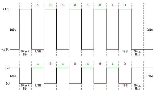
Figure 3. Timing diagrams showing TTL and RS232 logic and voltage values.
(Source: Sparkfun)
Connecting an Arduino to a PLC
To wire an Arduino to a PLC requires a small electronic circuit capable of converting TTL to RS232 signals. Both Tx (transmit) and Rx (receive) lines of the two devices must be connected to communicate over these digital communication serial lines. On the Arduino, dedicated digital pins D0 (Rx) and D1 (Tx) are used for embedded serial communication applications. Using pins D0 and D1 other than for data communications will cause an electrical short circuit of these to digital pins to occur on the Arduino.
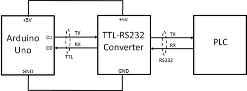
Figure 4. A TTL-to-RS232 converter circuit allows the Arduino to communicate with a PLC.
(Source: Don Wilcher)
Several embedded hardware manufactures provide a variety of breakout boards and voltage shifter devices to accomplish the TTL-to-RS232 conversion. Sparkfun Electronics has developed a shield that conveniently sits on top of the Arduino, providing the TTL- RS23 converter circuit. The IC used on the shield for the voltage shift process is a Maxim MAX232. Also, the Sparkfun shield allows all of the Arduino analog and digital pins to be available by way of female inline headers.
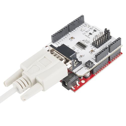
Figure 5. The TTL-RS232 shield allows an Arduino to communicate directly to a PLC using a serial cable.
(Source: Sparkfun Electronics)
The embedded software required to establish a physical connection between the devices is the SoftwareSerial code located in the Arduino IDE (Integrated Development Environment) programming tool. Additional examples of Arduino-PLC applications can be searched on the Web. Also, the Arduino Modbus PLC with RS232 and Mango M2M HMI is a practical example of how these two embedded platforms can be used to develop a home automation application.
Don Wilcher is a passionate teacher of electronics technology and an electrical engineer with 26 years of industrial experience. He’s worked on industrial robotics systems, automotive electronic modules/systems, and embedded wireless controls for small consumer appliances. He’s also a book author, writing DIY project books on electronics and robotics technologies. His latest book, Make: Basic Arduino Projects, published by Maker Media, is on the Alabama State Department’s approved Career and Technical Education (CTE) reading list. He’s currently developing 21st century educational training products and curriculum focusing on Internet of Things (IoT) and Industrial Physical Computing for makers, engineers, technicians, and educators. Besides being an Electrical Engineer, he’s a Certified Electronics Technician with ETA International and Alabama State Certified Electronics Instructor.
Like reading Design News? Then have our content delivered to your inbox every day by registering with DesignNews.com and signing up for Design News Daily plus our other e-newsletters. Register here!
You May Also Like
Editors' Choice

.jpg?width=300&auto=webp&quality=80&disable=upscale)


Jun 4 - Jun 6, 2024
Jun 4 - Jun 6, 2024
Innovation in automation starts here. Discover and collaborate on automation solutions that are revolutionizing the entire production lifecycle — from design to production to market — and sharpen your competitive edge. ATX South is part of IME South, a six-in-one expo offering the latest insights & solutions spanning medtech, packaging, automation, plastics, design, & processing.
Register Now