ROS 101: Monitoring a Push Button Switch with the Robot Operating System
This tutorial uses a simple tactile push button switch to teach some basic concepts of the Robot Operating System (ROS).
November 6, 2019

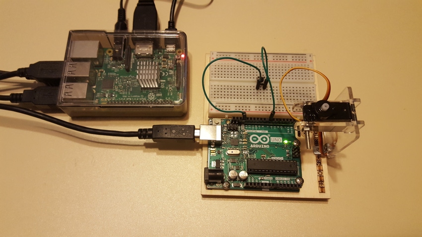
We can investigate the fundamentals and basic concepts of the Robot Operating System (ROS) using only an Arduino, a Raspberry Pi, and a tactile push button switch. With these electronic components, we can easily demonstrate the ROS concept of publishing a topic when the tactile push button switch is pressed.
This hands-on tutorial, adapted from the ROS.org wiki, takes several minutes to setup and will display a True or False boolean message on a Linux terminal.
The ROS model for publishing the Boolean message is illustrated below:

The push button ROS circuit is quite simple in terms of its component count. The circuit consists of a tactile push button switch wired to the digital pin 3 of an Arduino Uno. The tactile push button switch provides a digital logic low signal enabled by a software pullup resistor of the Arduino code.
Here's a circuit schematic diagram:

Here as well is an equivalent breadboard electrical wiring diagram showing the attachment of the tactile push button switch to an Arduino Uno:

The Arduino software code (sketch) for enabling the pullup resistor for the tactile switch is provided next:

With the electrical wiring of the tactile push button switch to the Arduino Uno completed, the electronics prototyping platform can be attached to the Raspberry Pi 3 B+ using a USB cable. The B connector mates with the Arduino. The A connector attaches to the Raspberry Pi 3 B+ USB port.

Here is the actual prototype of the ROS push button tutorial:

The next phase is to upload the push button code to the Arduino. With the Arduino Integrated Development Environment (IDE) opened, go to Rosserial Arduino Library. With the mouse, select Button_ example.

To activate the ROS Master to monitor the topic (pushed) is initiated by pressing a tactile push button switch. Opening a Linux terminal and typing the ROS command roscore after the prompt ($) will start the ROS Master code for push button monitoring.

To allow the data communication between the ROS Master and the topic pushed to be established, the rosserial command is typed next.
Opening a new Linux terminal window and typing the command rosrun rosserial_python serial_node.py /dev/ttyACM0 will establish a serial communication link between the ROS Master and the pushed topic.
The baud rate for this communication link is set at 56700 baud. The publisher node will transmit the Boolean message of True or False based on the tactile push button’s event or triggered status.

An example session of the ROS button displaying the Boolean value as the tactile push button switch is being activated is illustrated in the following figure:

To view the published topic pushed boolean data, another Linux terminal window is open. After the prompt, type the ROS command rostopic echo pushed to view the Boolean data on the opened Linux terminal window.
For further experimentation with this ROS monitoring application we could replace the tactile push button switch with another electrical or electronic switching device such as an electromechanical relay’s normally open (N.O.) or normally closed (N.C)] contacts, or a transistor based digital switch. You can also create a pulldown resistor by modifying the push button code previously shown and observe the software behavior of the triggered switch.
For reference material on how to get started with ROS, read the introductory Design News article here.
RELATED ARTICLES:
[All images courtesy Don Wilcher]
Don Wilcher is a passionate teacher of electronics technology and an electrical engineer with 26 years of industrial experience. He’s worked on industrial robotics systems, automotive electronic modules/systems, and embedded wireless controls for small consumer appliances. He’s also a book author, writing DIY project books on electronics and robotics technologies
About the Author(s)
You May Also Like


