Gadget Freak Case #264: Drink Delivery Vehicle – Inverted Pendulum
October 17, 2014

The DDV-IP is an inverted pendulum driving machine. DDV-IP stands for Drink Delivery Vehicle - Inverted Pendulum. The concept is a two-wheeled self-balancing robot that can deliver cold beverages to thirsty folks on hot summer days. A wireless RF remote enables manual control of the device beyond the act of self-balancing. All of the features of the DDV-IP result in an effective delivery vehicle while providing entertainment to the user.

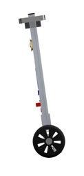
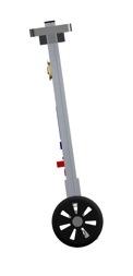
To describe how the DDV-IP operates, a side view of the device is pictured in Figure 1. The concept is similar to balancing a broom on your fingertip. The pivot point of the device is its center of gravity, located near the top center. As the center of gravity departs from perfectly vertical, it begins to accelerate downward toward the ground. The inertial motion unit consists of accelerometers and gyroscopes that allow the angle of the center of gravity and the rate at which it is accelerating toward the ground to be calculated. This information is sent to a PID controller which is programmed on an Arduino Due. The PID controller then determines the correction speed and direction required to set the pulse width modulated motors in order to return the robot to the neutral position. A trimming potentiometer is used to adjust the desired neutral angle upon startup. The neutral angle set point, as well as the current angle, can be monitored via the LCD display. This allows for the device to be fine-tuned for a given location as the unit is sensitive to changes in floor surfaces and ambient temperatures. With no input from the remote control, the DDV-IP will remain upright and near stationary.
As a safety feature, when the DDV-IP is turned on, the motors will not power up until the unit is raised to the vertical position. At this time, a warning tone sounds to let the user know that the DDV-IP is fully activated and the motors will begin to spin.
The remote control operates wirelessly via a 2.4 GHz radio module, performing two-axis control of the DDV-IP in addition to lighting control. The forward and backward motion of the DDV-IP is controlled via the y-axis of the joystick, while turning is controlled by the x-axis of the joystick. The forward and backward motion is created by proportionally adjusting the neutral angle with the amount of y-axis joystick travel. Button 1 on the remote control turns the entertaining PIC controlled light show on and off. The light show consists of a patterned routine of super bright LEDs mounted in the cup holders. Button 2 is a design consideration that allows for future implementation of additional functionality.
The construction of the framework of the DDV-IP is relatively straightforward. Extruded aluminum bars were used to make a sturdy frame while a simple acrylic sheet provides a mounting surface for all of the hardware. All hardware was mounted on 1/4-inch risers to allow ample cooling and spacing. Specific fasteners are needed to utilize the channel on the aluminum bars. The lead acid battery was placed at the top of the unit to increase the moment of inertia and aid in balancing.
One significant feature that is included in the design of the DDV-IP is the homemade printed circuit board. This PCB serves as the main hub to which the majority of the wiring gets initially routed to. Traces on the PCB organize the incoming wires such that the exiting wires can be run cleanly in blocks to the Arduino Due. The PCB hub greatly reduced the amount of wires strewn about the device and adds to the aesthetic value. Reliable connections were made using pin headers.
The top tray consists of an acrylic sheet that is fastened to the top of the extruded aluminum bars. The cup holders are doughnut-shaped acrylic cutouts with holes drilled in to accommodate the LEDs. The LED controlling PIC and accompanying wiring is mounted under the tray. The slave PIC is wired to the Arduino Due located on the main board. The Arduino Due is the brain of the device and contains the PID controller as well as the main program.
The motors required a custom bracket to attach to the channel of extruded aluminum bars. Aluminum angle was used and two holes were drilled in each bracket to fasten to the channels of the extruded aluminum. Six small holes needed to be drilled in each of the aluminum angle to attach the motors.
Click here to view Table 1.
Do you have a Gadget Freak project you would like the world to see? Send a brief description of your gadget and a photo to Executive Editor Jennifer Campbell.
{videoembed|275195}
Check out the Best of Gadget Freak -- Volume 2 Technology Roundup to see some of the best gadgets that your peers have created.
When you are finished, be sure to check out Best of Gadget Freak: Vol. 1.
About the Author(s)
You May Also Like


