Building a Wall/Desk Clock With a Customized Arduino and NeoPixel Displays
Need a new DIY project? Or help keeping track of time? Try building this custom digital clock.
February 26, 2024
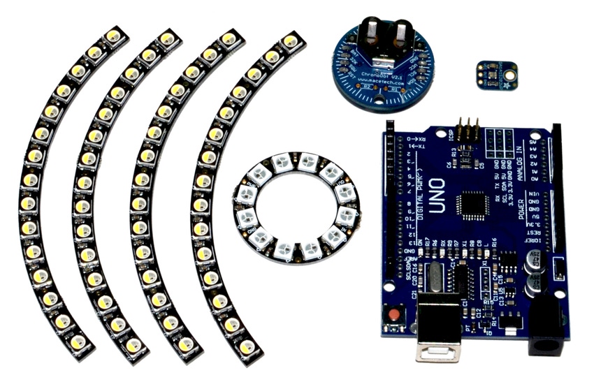
Every maker needs a geeky wall clock and the geekiest way to get one is to build your own. With so many modular and open-source options, building your own decorative clock is far from the most difficult design exercise, but it can be great fun for the expert as well as a basic tutorial from the novice. The clock design I’ve chosen to pursue has an Arduino at its heart. I’ve taken it a step further and designed and built a custom PC board based on the open-source Arduino Uno circuit.
Digital clocks are not complex devices. They require a precision oscillator, some frequency dividers, displays, and display drivers. You can build one with discrete logic or, much more easily, with a microcontroller. I’m opting for the microcontroller route. From there, I’ll add an RTC (real-time cock) chip and a set of NeoPixel RGB addressable LEDs for the display.
Here's a list of parts:
Four x NeoPixel 1/4 60 Ring segments: 5050 RGB LED w/ Integrated Drivers
NeoPixel Ring: 12 x 5050 RGB LED with Integrated Drivers
Arduino Uno (or any just about any Arduino of your choosing)
Time for a Solderless Proto Board
I prototyped the clock with the modules listed above. To that set, I added a wireless protoboard, an LED as a status indicator, and a couple of pushbutton switches to be used to set the clock and a battery backup for the RTC. I put the photo transistor light sensor there in case I want to adjust NeoPixel brightness based on ambient light.
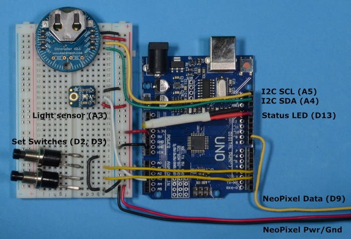
Prototyping the NeoClock with an Arduino Uno. DUANE BENSON
NeoPixels operate with three wires: power, ground, and data. They come in RGB or RGBW (red, green, blue, white) versions. I’m using the RGB. They are rated to operate at 5 volts, but I’ve had good success running them directly from LiPoly batteries in the 3.5 to 4.2 volt range. Each pixel is connected to the next in a daisy chain. There is no termination needed on the last pixel. It is just left unconnected.
Soldering up the Display
Connect GND to GND and 5 V to 5 V on all four ring joints. Daisy chain Data Out on the 12-pixel mini ring to DIN on one of the ¼ ring segments. Leave “DOUT” unconnected on that segment and connect the other three DIN to DOUT on the other ring joints.
Daisy chain soldering the mini ring and large ring. DUANE BENSON
My first version used the 60-pixel ring alone as the complete display. I encoded hours, minutes and seconds through the use of different colors. However, I like the look of an inner ring for the hours better so I added that to my second custom PC board. Depending on your preference, you can include or leave out to inner 12-pixel ring and modify the software accordingly.
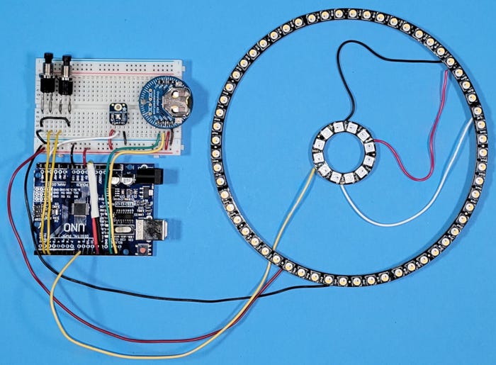
The final clock, before custom PCB. DUANE BENSON
Creating a Custom PCB for the Clock
Making your own PCB based on the Arduino is deceptively easy. If you have PCB design experience, it will be a light load to do so. The Arduino design is available in a number of CAD formats. Start with the schematic, add in your customization, and jump to layout. If you don’t have PCB design and layout experience, I wouldn’t pick this as your first project, but as a second or third, you should be able to do just fine.
My first incarnation was to be a small board that fit inside the contours of the 60-pixel ring. I chose the Arduino Leonardo schematic. The Leonardo uses an Atmega32U4, which has built-in USB connectivity. It makes the PCB easier, with one less chip and fewer passive components. For the final version, I went with the original Atmega328P and an FT231XS. With this arrangement, you get a little more program code and a little more flexibility with the USB connection.
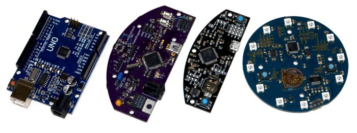
Evolution of the NeoClock custom PCB. DUANE BENSON
I like a lot of flexibility in my boards. The pushbutton switches can be used as soldered directly on the board, as I do in my wall version, but I also have pin header spots so that wires can be soldered and the switches can be used on a remote front panel someplace. The I2C is broken out and can be used to add in other peripherals like an accelerometer or Bluetooth LE radio connection. And I have five miscellaneous GPIO out, each with its own dedicated power and ground. The Arduino programming port, for uploading firmware, also doubles as an SPI interface. The USB micro-B connector, pushbutton switches, and the coin cell holder can be soldered onto either the top side or bottom side of the PCB.
Custom PCB Assembly
I’ve included a link to my GitHub repository with all files included. The CAD file is a two-layer design in Eagle. I’ve had variations of the board fabricated at Sunstone Circuits and at OSHPark. Both have delivered a solid product and are great to work with.
The smallest component is an 0603 size phototransistor. All of the passives are 0805. The 20-pin SSOP for the FTDI chip is the smallest pitch part. I have hand-soldered a number of these without special equipment. There are plenty of guide videos for hand-soldering surface mount hand on YouTube. Watch a few and you should be good to go. Again, not a good first surface mount project, but not too advanced for most people after a little practice.
After assembling the board, you will need to program the Atmega328P. The Arduino site has a good tutorial for flashing the chip using ArduinoISP as an in-circuit programmer. Your standard Arduino would be “programmer” and the clock would be the “target.” Solder in a 2x3 pin 0.1” header to the connecter shown in the photo below. Then wire the programmer Arduino pins to the clock as shown.
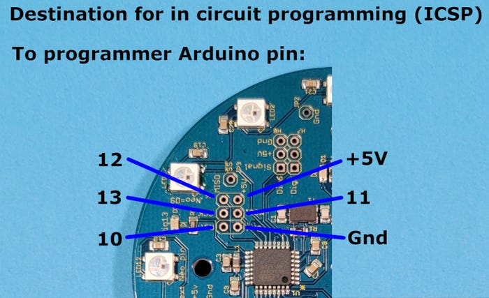
Flashing the Arduino code into the microcontroller. DUANE BENSON
Once you have flashed the Arduino firmware, you are ready to program in the clock code and go. Connect to your computer with a USB micro-B connector. Set the Arduino IDE to the “Uno” setting for your choice of board. The code is available in the GitHub repository listed below.
The Software Setup
Any microcontroller would work for this project, but I chose an Atmel (Microchip) Atmega328P based Arduino. This project has a light computing load and the Arduino system has drivers for all of the hardware I am using. The Arduino IDE is easy to install and use and the language has C-like syntax that would be familiar to anyone with C, C++, Javascript or other C-like languages.
NeoPixels are individually driven by a small microcontroller built into each pixel. They are daisy-chained together and are sent an array with RGB (or RGBW) values for each pixel in sequence. Each pixel takes the top RGB value for its setting and passes the rest on. The protocol is delivered at a frequency of 800 KHz, but all of the specific details are handled by the Arduino driver.
Arduino software has three basic sections: setup, main loop, and helper functions. In setup, I configure the I/O pins, read the RTC, and initialize the NeoPixels. If the RTC detects that it has lost power, or if the Usr1 button is pressed at power up, the clock will jump to set time mode.
The main loop first reads the two switches and then runs through a short state machine to decide what action to take from the switches. After that, it sets brightness, reads the RTC, and sets and displays the time, all through helper functions.
Operating the Clock
Clock operation is pretty easy. After powering it up, press both buttons simultaneously to enter time setting mode. The yellow LED just to the right of the “12 o’clock” NeoPixel will light up to indicate time-setting mode. Press the left button to decrease the hour and the right to increase. Press both buttons again to set the minutes. Use each button to move the minute forward or back as you did with the hours. Then press both buttons a third time to exit time setting mode. Note that as programmed, the hour markers on the large outer ring will glow orange in the AM and pink in PM. You will see the change if you move past noon or midnight when setting either the hours or minutes.
When not in time-setting mode, pressing the left button will decrease the clock brightness and pressing the right button will increase it.
Resources for Building a Clock With a Customized Arduino and NeoPixel Displays
GitHub repository with all files
Expansion and Variations on the Theme
If you have access to a 3D printer, I have included .STL files for the clock face and a table top standing bracket. In addition to the wall hanging and desk versions, I 3D-printed a bracket for LiPoly battery and a battery charger PCB I designed. The combination makes for a battery-operated clock with, depending on the size of battery and how bright I set the NeoPixels, up to about 30 hours per charge.
If you want to do more with your clock, say, turn it into a clock-faced robot, you can access the I2C bus; the ISP bus; analog inputs A0, A1, and A2; and digital I/O ports D6 and D5.
About the Author(s)
You May Also Like


