Mesh Morphing Explained
Learn the advantages of mesh-morphing. Proper mesh morphing can lead to faster run-times and predictions.
January 24, 2020

This Design News interview with Marco Biancolini, founder of RBF Morph, offers insight into the advantages of using mesh morphing.
Design News: What is mesh-morphing; what kind of advanced features or capabilities can it have, and how does proper mesh morphing lead to faster run-times and predictions?
Biancolini: Mesh morphing consists of the adaption of a computational grid adopted for computer aided engineering (CAE). For instance, the solid or shell mesh of a structural part ready to be processed by an FEA solver, or the volume mesh complete with boundary conditions for a CFD solver, can take a new shape by just updating nodal positions. This means that the topology of the mesh (nodes count, cells count, connectivity) stays the same. Only the x,y,z coordinates of the nodes in the part of the model undergoing a shape modification are updated.
Mesh morphing can be used for different purposes: create shape parameters (i.e. change a length, an angle a thickness), move onto a new known shape (i.e. as manufactured, as designed by CAD), move onto a shape predicted by the CAE solution (automatic shape optimization with adjoint or BGM), and/or support multiphysics (move CFD mesh according to the evolution of the FEM-connected one, enable erosion/deposition).
Usually mesh morphing is faster than remeshing for a number of reasons: it avoids “remeshing noise” (having the same mesh adapted means the effect of a parameter is not confused with the effect of a new mesh structure), so variation effects can be assessed even with a coarser mesh. The CAE model can be updated on the background keeping all the original settings (boundary conditions). The update of nodal positions usually requires less computational efforts vs a full mesh regeneration. Creating shape parameters with mesh morphing is faster than creating a parametric CAD model.
|
Examples of RBF Morph design technology in (left) a turbine blade and (right) a study of surgical screws in a vertebra. (Left image courtesy of Rina, right image courtesy Spinner) |
DN: What are radial basis functions (RBF)? What is reduced-order modelling? How do they improve meshing?
Biancolini: RBFs are a mathematical tool capable of interpolating known fields on a cloud of points. Mesh morphing defines a displacement field on a cloud of source points (usually some of the surfaces/curves of the CAE mesh) and then propagates it on a cloud of target points (usually the nodes of the volume/surface mesh of the CAE model undergoing adaption). The method fits very well with mesh morphing needs: its meshless nature allows you to easily manage partitioned meshes used for high-performance parallel computation (HPC); its node-wise nature allows you to have full control of specific areas. The computational cost of RBF can be very high, so specific algorithms (Fast Radial Basis Functions) are required to enjoy such benefits for industrial applications.
Reduced order models (ROM), as suggested by their name, are numerical models of a system (fluid, structure or other physics) capable of working very fast (typically in real time). ROM are defined by adopting data-compression algorithms and applying them to many different instances (known also as snapshots) of the original model to be reduced.
RBF and ROM are not intended to improve meshing but—as I’ll explain in more detail when we discuss the link between meshing and Digital Twins (see below)—rather allow for a link between CAE/meshing and the implementation of real time Digital Twins. RBF is in fact a method of mesh morphing that supports the automatic generation of shape variations of the original mesh. Some distortion of the cells undergoing the deformation (stretching/compression) usually occur and a good mesh morphing method must preserve the quality of the morphed mesh. RBF are proven to be one of the best solutions nowadays available to implement high quality mesh morphing: the core of the mesh is adapted with minimum distortion, and the distribution of mesh size close to the surfaces (boundary layers to capture the flow, refinement layers to capture stress raisers) is very well preserved.
DN: When it’s said that that large solver capacity and high-performance computing are available and considered standard resources, what are the new solve capacities and what were they a few years ago, and what do you mean by high-performance computing? How is that measured in your view?
Biancolini: For CAE applications the trend is to go with finer meshes because we now have such high computational power available. The figures are different for fluids and for structures. In 2009 a large mesh for external aerodynamics in the automotive industry was in the range of 50 million cells and a 250 million-cell one was common for top applications such as Formula 1. Ten years later it’s now common to go beyond 100 million for standard usage and reach the billion level for top applications. For FEA the figures are smaller: 250k was quite large ten years ago, 1 million is common today. Mesh morphing is helpful for any size of model and the complexity of the morphing action grows with the size of the mesh to be updated. In the coming decades we expect to grow model size up to the hex scale.
HPC uses large clusters that allow intense parallel calculations (thousands of CPU cores and terabyte of memory available on a pay-per-use basis from cloud-resource providers) or high-end workstations/dense servers (a 100 cores/ 256 Gb RAM is in the 20-30k Euro price range); while intense calculation power is allowed by GPU as well, not all CAE technology is available for a GPU implementation. RBF can be accelerated by adopting fast algorithms and parallel calculations (both CPU and GPU).
The level of performance needed is a matter of usage. If an interaction with the user is required, it is of paramount importance to have a responsive application and so the compression of computation time of mesh morphing setup is mandatory to avoid delays. For batch usage performance of mesh morphing, the overhead must be balanced against CAE time. With RBF Morph it is typical that the time required to update the mesh is less than 2% of the time required to compute the CAE solution. For transient simulations the extra cost for a single step is usually lower than 5% of the time required by the CAE solver.
|
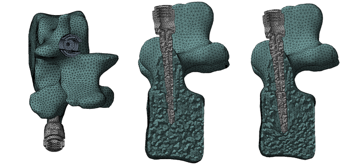
A high-fidelity, patient-specific FEA model representing a vertebra and two prosthetic screws is created; mesh morphing allows for updating of the diameter and the length of the screw to optimize individual patient treatment. (Image source: RBF Morph) |
DN: What is the link between FEA/meshing and digital twins?
Biancolini: ROM are key enablers of Digital Twins (DT): the original system is modelled adopting high-fidelity CAE methods (such as CFD and FEA) considering multiple configurations (different shapes, different boundary conditions or changing whatever is an input of the model) that are screened adopting a large amount of HPC (ROM creation); the compression stage allows for squeezing the model into a lighter and more portable piece of software (a standard is the adoption of .fmu-file format). Obtained ROM can then be used as a piece of a complex simulation workflow or embedded on a physical asset to enable the digital twin.
Mesh morphing is an excellent companion to ROM because to have a ROM with variable shape (think for instance at the angle of a deflector adopted to control a flow field) the mesh topology must be the same; this is related to the nature of compression methods that extract the ROM.
DN: Has FEA been lacking in supplying the needed features for Digital Twin creation?
Biancolini: FEA is not lacking in providing the needed features. FEA and generally speaking CAE (that could be FEA/CFD/multiphysics) is a piece of the puzzle toward generation of a digital twin. The digital high-fidelity model of the asset is defined according to best practices that are very well established for the design process. If shape parameters are needed, mesh morphing is added to the workflow so that multiple instances of the same asset working at different configurations becomes available. All the instances are then fully explored by adopting HPC. Strictly speaking this is already a digital twin. The performance of the system can be predicted with high fidelity and used for the maintenance of the physical asset. However, this approach has some limitations: a new evaluation of the digital twin comes with the cost of HPC and requires access to the CAE software and the proper infrastructure. To gain portability and fast access the ROM strategy comes in handy. The behavior of the high-fidelity model is accurately reproduced adopting data compression; furthermore, the ROM becomes portable and can work without the original CAE infrastructure.
DN: What types of FEA software are needed for digital twins/IoT and why?
Biancolini: Any kind of CAE software can be used for this purpose, not only FEA. Which software is adopted for a high-fidelity simulation depends on the specific application. There is a wide choice of open source/commercial CAE solvers offered by ISV. Much of this software is multi-purpose but we know very well that for each field there are preferred choices, and this could make the generation of Digital Twins quite complex, especially if the high-fidelity simulation requires multiple solvers from different vendors. The principal actors in CAE are committed to offering out-of-the-box solutions suitable for the creation of DT.
|
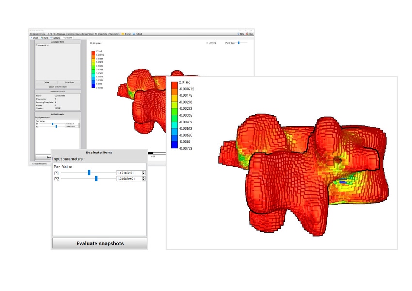
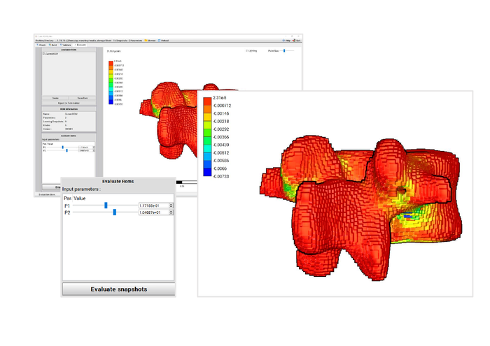
The Viewer of Twin Builder, powered by a mesh-less and solver-independent rendering tool, allows for interaction with the Digital Twin of the vertebra. The sliders P1 and P2 allow for updating, in real time, the diameter and the length of the screw and to inspect how the minimum principal strain changes. (Image source: RBF Morph) |
To explain the full workflow let’s consider the example of the spine application investigated in the Spinner project (spinner-eid.eu) where both ANSYS and RBF Morph are participating. A high-fidelity FEA model is defined adopting the actual patient vertebra geometry with the prosthetic screws positioned so that an evaluation of the stress on the prosthetic part and on the patient bone tissue is possible (ANSYS Mechanical). Then an offset of the positioning of the screws and of their size is introduced by mesh morphing (RBF Morph ACT Extension): let’s say that we have two parameters for the screw size (length and diameter) and four parameters for the positioning (vertical and side adjustment for both vertebrae). The six-dimension parametric shape is then evaluated automatically (ANSYS Design Explorer) and 200 configurations are quickly evaluated using HPC.
Results are compressed adopting a software for ROM generation (ANSYS Twin Builder) and the ROM behavior can be inspected and validated in the CAE platform (ANSYS Twin Builder Viewer). The ROM can then be exported in a .fmu file. Such a file can be accessed without the need for the CAE platform and moved to the medical researchers (for instance adopting MATLAB) or to the medical gears (for instance embedded in the standard imaging tool commonly adopted by medical doctors and medical technicians). The interactive digital twin of the spine repair could help the planning or can assist during the medical intervention via augmented reality in which the digital images are computed in real time by the digital twin.
Marco Biancolini is Associate Professor of Machine Design at the University of Rome, and an expert in advanced CAE workflows. He has contributed to a wide variety of European Community projects such as RBF4AERO, Fortissimo, RIBES, Cloudifacturing, and MeDiTATe. He is the author and owner of RBF Morph software and an honorary member of the Technet Alliance.
DesignCon: By Engineers, For Engineers January 28-30: North America's largest chip, board, and systems event, DesignCon, returns to Silicon Valley for its 25th year! The premier educational conference and technology exhibition, this three-day event brings together the brightest minds across the high-speed communications and semiconductor industries, who are looking to engineer the technology of tomorrow. DesignCon is your rocket to the future. Ready to come aboard? Register to attend! |
About the Author(s)
You May Also Like


.jpg?width=300&auto=webp&quality=80&disable=upscale)

