

Sign up for the Design News Daily newsletter.
7 Steps to Debugging With a Serial Viewer
Here's how you can set up a serial viewer to help you debug your embedded system code.
Jacob Beningo
May 16, 2016
3 Min Read
.svg?width=850&auto=webp&quality=95&format=jpg&disable=upscale "7 Steps to Debugging With a Serial Viewer")
A picture is worth a thousand lines of code. Embedded software developers have been plagued for decades with a lack of images and visual aids to help them understand how an embedded system is actually executing its code. Sure we have UML and other design aids, but with the advent of serial viewer capabilities, developers are now finally able to glimpse into the heart of an embedded system as it executes code and see how it is behaving.
Let’s examine how we can get a serial viewer up and running using a NXP K64F Freedom Board, a Segger J-Link Ultra+ with System Viewer, FreeRTOS, and Atollic TrueSTUDIO.
Step 1 – Download and Install the Tools
In any development environment there are any number of tools that could be selected that could get the job done. In this particular instant, I downloaded and installed the following tools for my development environment:
To help install the Processor Expert Plug-in, I found an application note on the Atollic website entitled “Integrate Freescale Processor Expert with Atollic TrueSTUDIO” that had step-by-step instructions on how to install the plug-in. The other applications were straight forward to install using an installation wizard.
Step 2 – Create a Project
The first real step with any project is to create a project, configure it for the board, and get a baseline RTOS up and running that can blink an LED.
The use of the Freedom Board K64F turned out to be a good choice of development kit as Processor Expert already had the board included among the supported development kits list (Apparently not all Freedom Boards are supported by Processor Expert).
Stepping through a simple wizard allowed the bare-metal project to be created but the real power of a serial viewer is its ability to visually display what is happening to onboard tasks.
Step 3 – Configure FreeRTOS
The next step with the project was to setup FreeRTOS. A quick look at the FreeRTOS website revealed that there weren’t any example projects already setup for the K64F Freedom Board. Luckily, there is no need to port FreeRTOS. Instead, a developer can simply search through the processor expert component library and add the FreeRTOS component to the project. In order to configure it properly, it is recommended to set the SysTick timer within the ARM core as the RTOS timer. Figure 1 shows an example of what the project looks like with the FreeRTOS component added to it.
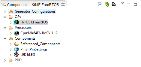
Figure 1: Processor Expert FreeRTOS Component.
Step 4 – Add Some Example Code
Even though the FreeRTOS component has been added to the project, there aren’t any tasks added to the application. Sure the FreeRTOS scheduler will run, but there isn’t anything to do yet. Creating a few blinky LEDs is always a great way to start off any professional software endeavor. As luck would have it, there is a tri-color LED onboard the K64F Freedom Board containing a red, blue, and green LED.
The example code will create one task for each of the LEDs and look something similar to Figure 2. Note that the entire source project can be downloaded here.
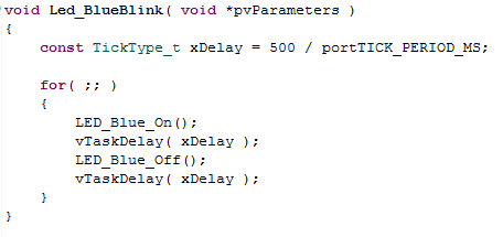
Figure 2: LED Task code listing.
Steps 5-7: Next Page
About the Author(s)
You May Also Like
Editors' Choice
.jpg?width=300&auto=webp&quality=80&disable=upscale)


Jun 4 - Jun 6, 2024
Jun 4 - Jun 6, 2024
Innovation in automation starts here. Discover and collaborate on automation solutions that are revolutionizing the entire production lifecycle — from design to production to market — and sharpen your competitive edge. ATX South is part of IME South, a six-in-one expo offering the latest insights & solutions spanning medtech, packaging, automation, plastics, design, & processing.
Register Now