Sign up for the Design News Daily newsletter.
Obey Your Cat's Demands and Build an Automated Food Dispenser 26879
Your cat demands to be fed on time. With some technical know-how and a 3D printer you can build your own automated cat food dispenser.
September 27, 2016
9 Min Read
.svg?width=850&auto=webp&quality=95&format=jpg&disable=upscale "Obey Your Cat's Demands and Build an Automated Food Dispenser")
Cat owners know that few things make their pets happier than getting their food on time. But sometimes those times aren't always the most convenient (for humans at least). You can't leave a bowl full of food (if you want to still be able to lift your cat anyway). So it needs to be dealt out in small portions.
Gadget Freak contributor Kerry Erendson combined some engineering know-how with some skilled 3D printing to create an automated cat feeder for his cat, Squishy - who prefers to be fed precisely at 10 a.m. and 3 p.m. every day.
The goal was to be able to set the unit to vend dry cat food at programmable times throughout the day. To allow this, there is an LCD on the front panel with three "soft switches," i.e. switches whose functions are defined by software. These buttons take on the functions labeled above them on the bottom line of the display.
The main screen's top line shows current time. The bottom line labels the left button "MENU" and the right button "ON/OFF." Pushing the right button on this screen toggles the label between ON and OFF. The bipolar LED to the right of the display is green when the unit is ON and unlit when the unit is OFF. This ON/OFF status determines whether the unit will "vend" when it reaches a programmed vend time. The LED allows you to check its status from across the room without looking at the LCD. The LED turns red if an error is detected.
The "MENU" button takes you through a series of choices "Program?", "SetTime?" & "VendNow?" (see "Dispenser Operation Manual.doc" for details).
Well, Squishy loves her feeder, finding it far more reliable than the humans who used to do that job.
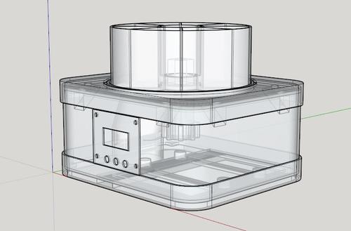
The unit uses eight different 3D-printed parts:
1) Food Bin that sits on top under the clear cover.
2) Top Surround that you slide up & off to get at the cover and bin.
3) Spacers are little tabs/washers under the Top Plate's screws (8 screws total)
4) Top Plate has the round area where the Food Bin sits and rotates.
5) Enclosure is the white bulk of the housing, has integral curved chute inside.
6) Bezel has LCD window opening and holes for pushbuttons, all matching the PCB layout.
7) Bottom Surround provides the base structure and solid cross member to support the motor.
8) Rotator has a D-shaped hole all the way through to mate with the motor's output shaft. At the bottom it has a section with 8 "bumps" which actuate the microswitch. The rest of the length is a square that matches the center of the Food Bin that slides down on it.
Click the image below to see the build process for the cat food dispenser.
Click here to download the full build instructions, including SketchUp files, firmware, and schematics.
Let's start at the bottom and print the bottom surround. This will give you an overall feel for the size. I used PLA for the bottom surround and for that matter everything except the main body, which is the white enclosure section, and the white "Rotator." Using ABS for these two parts let me take advantage of the shrinkage that ABS exhibits. This provided clearance for the enclosure to slide inside the bottom surround without having to account for it in the design.
Parts List:
Part | Value | Device/Package |
| Description |
BAT1 | BR1225A/FA | Battery |
| |
|
|
|
|
|
C1 | 0.01 | CNONPOL-0603 |
| Capacitor, Non-Polarized, SM |
C2 | 0.1 | CNONPOL-0603 |
| Capacitor, Non-Polarized, SM |
C3 | 10µF | CPOL-3216/A |
| Capacitor, Polarized, SM |
C4 | 0.1 | CNONPOL-0603 |
| Capacitor, Non-Polarized, SM |
C5 | 0.1 | CNONPOL-0603 |
| Capacitor, Non-Polarized, SM |
C6 | 1µF | CNONPOL-0805 |
| Capacitor, Non-Polarized, SM |
C7 | 1µF | CNONPOL-0805 |
| Capacitor, Non-Polarized, SM |
C8 | 0.01 | CNONPOL-0603 |
| Capacitor, Non-Polarized, SM |
C9 | 0.1 | CNONPOL-0603 |
| Capacitor, Non-Polarized, SM |
C10 | 0.01 | CNONPOL-0603 |
| Capacitor, Non-Polarized, SM |
C11 | 0.01 | CNONPOL-0603 |
| Capacitor, Non-Polarized, SM |
C12 | 0.01 | CNONPOL-0603 |
| Capacitor, Non-Polarized, SM |
C13 | 0.1 | CNONPOL-0603 |
| Capacitor, Non-Polarized, SM |
C14 | 0.1 | CNONPOL-0603 |
| Capacitor, Non-Polarized, SM |
C15 | 10µF | CPOL-3216/A |
| Capacitor, Polarized, SM |
C16 | 0.1 | CNONPOL-0805 |
| Capacitor, Non-Polarized, SM |
C17 | 10µF | CPOL-3216/A |
| Capacitor, Polarized, SM |
D1 | S1GB-13-F | Diode, S1BB |
| Allied #70438453 1A 100V Diode SMB pkg Diodes Inc, notch or line is cathode |
J1,J2,J3,J6,J7,J8,J9,LED1 | .1" sp. 2-way male header |
|
| (J7,J8,J9 used on hand-wired bd., put at LED1 to allow harness to front panel) |
J4 | .1" sp. 6-pin dual row male header | BKGD-1-JDR6 (µC prog. conn.) |
|
|
J5 |
| .1" sp. 16-way male header |
|
|
L1,L2 | MI0603J600R-10 | INDUCTOR-0603 |
| ferrite, Allied #70065459 |
|
|
|
|
|
LCD1 | LCD 8-char. by 2-lines | New Haven Disp |
| Allied #70518050, non back-lit, Dispenser PCB has circuitry for a backlit LCD module but will need firmware mod to control it. Location also implies 16-way .1" sp. dual row female conn. for PCB and .1" sp. dual row male header for LCD module. |
LED1 | T 1-3/4 Bipolar Red/Green | thru hole |
| needs wiring harness to get it to front panel, also plastic LED panel mount |
PZ1 | AI-1440-TWT-12V-R | PIEZO2LEAD-.3"LS, .543" dia. |
| Piezo buzzer, 2 Leads, self-osc. |
Q1,Q2 DNI*,Q3 | MMBT3904 | MMBT3904-SOT23 |
| Transistor, NPN, General Purpose |
Q4 | 2N3904 | 2N3904-TO92 thruhole |
| Transistor, NPN, General Purpose, TO92 pkg. (used on hand-wired Relay Bd.) |
R1 | 4.7K | RESISTOR-0603 |
| Resistor, SM |
R2 | 220 | RESISTOR-0603 |
| Resistor, SM |
R3 | 100K | RESISTOR-0603 |
| Resistor, SM |
R4 | 10K | RESISTOR-0603 |
| Resistor, SM |
R5 | 4.7K | RESISTOR-0603 |
| Resistor, SM |
R6 | 4.7K | RESISTOR-0603 |
| Resistor, SM |
R7 | 10K | RESISTOR-0603 |
| Resistor, SM |
R8 | 10K | RESISTOR-0603 |
| Resistor, SM |
R9 | 10K | Trimpot |
| horiz., thruhole |
R10 | 10K | RESISTOR-0603 |
| Resistor, SM |
R11 | 10K | RESISTOR-0603 |
| Resistor, SM |
R12 | 10K | RESISTOR-0603 |
| Resistor, SM |
R13 DNI* | 10K | RESISTOR-0603 |
| Resistor, SM |
R14 | 10K | RESISTOR-0603 |
| Resistor, SM |
R15 | 10K | RESISTOR-0603 |
| Resistor, SM |
R16 | 10K | RESISTOR-0603 |
| Resistor, SM |
R17 | 10K | RESISTOR-0603 |
| Resistor, SM |
R18 DNI* | 0ohm | RESISTOR-0805 |
| Resistor, SM |
R19 | 200 | RESISTOR-0603 |
| Resistor, SM |
R20 | 3.3K | 1/4W 5% RESISTOR-thruhole |
| Resistor (used on hand wired relay bd.) |
RLY1 | NAIS TF2-5V | Relay DPDT |
| Relay DPDT 10-pin DIP NAIS TF2 (used on hand wired relay bd.) |
S1,S2, | S3 | SWITCH-PUSHBUTTON |
|
|
U1 | MC9S08QE128CLH | MC9S08QE128CLH, LQFP64 pkg |
| 64 lead µC, Motorola/Freescale/NXP |
U2 | TC54VN3002ECB | TC54VN4502ECB-SOT23 |
| Volt. Detector, 3-pin Allied #70046939 |
U3 | AT25256AN-10SU-2.7 | EEPROM, 32768 x 8 bits, SPI interface |
| SO8 pkg. (could use much smaller device but might need to mod. firmware) |
U4 | LP38690DT-3.3 | LP38690DT-3.3-TO252 |
| Volt. Reg. 3.3V fixed, LDO National LP38690DT-3.3 |
U5 | DS1338Z-33+ | RTC, I2C, SO-8pkg |
| RTC, I2C, 3.3V |
|
|
|
|
|
U6 | LM340T-5 | 7805V-TO220S-1 |
| Linear Voltage Regulator, thruhole, TO220 Standing up (vertical) Allied #70099955 |
XOSC1 | 4 MHz | Crystal Osc., 3.3V |
| 7 x 5mm pkg. |
Y1 | 32768Hz | Crystal, SM |
|
|
|
|
|
|
|
MOTOR1 | gear reduction motor | 6V |
| this was one I had in stock, don't know the specs, possibly 5 sec/rev |
| microswitch |
|
| microswitch with curved end actuator to detect "Rotator" bumps in both directions |
AC adapter | 6V 400mA |
|
|
|
|
|
|
|
|
|
|
|
|
|
Don't forget these are native SketchUp files, so you can open them to take measurements and modify them any way you wish. They were composed in the free version of SketchUp. You will of course also need the free plug-in / extension STL Exporter to create files for your CAM program. These designs are somewhat complex, so you should really have some level of 3D printing experience behind you before tackling them.
The Composite file is great for seeing how it all goes together, but don't forget to do any modifications in the individual file for that specific part. I would save modified files with a personalized name so you don't get versions confused.
Do you have a cool, original, homemade gadget you'd like to share with the world? Give us the details at DesignNews.com/GF, and you may receive $500 and automatic entry into our $6000 Gadget Freak of the Year contest!
[All images courtesy of Kerry Erendson]
You May Also Like
Editors' Choice


Jun 4 - Jun 6, 2024
Jun 4 - Jun 6, 2024
Innovation in automation starts here. Discover and collaborate on automation solutions that are revolutionizing the entire production lifecycle — from design to production to market — and sharpen your competitive edge. ATX South is part of IME South, a six-in-one expo offering the latest insights & solutions spanning medtech, packaging, automation, plastics, design, & processing.
Register Now