Designing Supercharged Connectivity and Autonomous Driving Systems
Key considerations to ensure reliable solutions for driver and passenger safety.

Sponsored by Littelfuse, Inc.
The electrification of automotive vehicles is continuing at a furious pace with the advancement of electronic technology. Much of the new technology concentrates on driver-free operation, and vehicle-to-vehicle, and vehicle-to-infrastructure communication. All of these are critical, especially as autonomous vehicles (AVs) become mainstream in the not-too-distant future. Figure 1 illustrates all the advanced technology integrated into an AV.
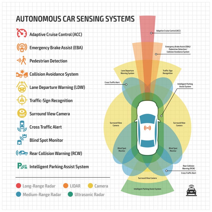
Figure 1: Advanced autonomous vehicle systems
However, the widespread adoption of autonomous vehicles is only possible if the electronic circuitry is reliable and robust to all electrical hazards. Today's electronics engineers can reduce the risk of critical circuit failures by providing the proper protection from overcurrent conditions, electrostatic discharges (ESD), transient surges, and reverse polarity for mission-critical AV subsystems, including:
Camera system
Radar system
Advanced driver assistance system (ADAS)
Vehicle-to-vehicle (V2V) or vehicle-to-Infrastructure (V2X) communication system
Emergency call (eCall) system
Smart Infotainment system
Figure 2 highlights some of these subsystems in a connected, autonomous vehicle. Each of the subsystems has recommended components for overcurrent and overvoltage protection.
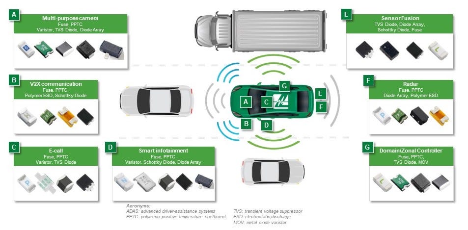
Figure 2. Connected, autonomous vehicle subsystems with recommended protection components
Protecting the emergency call (eCall) subsystem
Fortunately, electronics engineers can rely on rugged overcurrent and overvoltage protection components. The Automotive Electronics Council (AEC) develops standards to qualify components for use in the automotive vehicle environment. The standard, AEC-Q200, Stress Test Qualification for Passive Components, covers board-level electronic devices such as resistors, capacitors, inductors, thermistors, and varistors. An update to this standard now covers overcurrent protection devices. On March 20, 2023, The AEC published Revision E of the standard to define test qualification requirements for fuses. (For additional information, see the Updated AEC-Q200 Specifications for Automotive Applications, courtesy of Littelfuse.)
AEC-Q200 Revision E defines environmental stress tests such as temperature and humidity and physical characteristic stress tests such as mechanical shock, vibration, and other tests. A component must pass the specific test requirements to become AEC-Q200 qualified. Littelfuse has AEC-Q200 qualified components and has been preparing for the AEC to complete and promulgate Revision E. As a result, Littelfuse is the first manufacturer to offer a full line of AEC-Q200 Revision E-qualified fuses.
The AEC also has produced AEC-Q101, Failure Mechanism Based Stress Test Qualification for Discrete Semiconductors. This standard covers both diodes and transistors. Littelfuse has applied the AEC-Q101 qualification requirements to overvoltage protection components such as transient voltage suppressor (TVS) diodes, electrostatic discharge (ESD) diodes, and reverse polarity protection components such as Schottky diodes.
This article describes several components recommended to protect the connected AV subsystems. These components ensure the subsystems are robust to overcurrent and overvoltage conditions. The fuses are AEC-Q200 qualified, and the TVS diodes are AEC-Q101 qualified.
Protecting V2X communications subsystems
The V2X subsystems enable the vehicle to communicate with other vehicles and the highway infrastructure. Vehicle-to-vehicle (V2V) communication systems share information for collision avoidance, intersection management, emergency braking warnings, traffic jams, and road hazard alerts.
Vehicle-to-infrastructure (V2I) subsystems exchange information between a vehicle and elements of the transportation infrastructure, such as smart traffic signals and smart road signs for traffic management and optimization, intersection safety, information on road conditions, and other features that promote traffic flow and safety.
Figure 3 shows the circuit blocks of the V2V and V2I subsystems. The V2X system should include overcurrent and transient voltage/ESD protection consistent with the other vehicle subsystems. Fast-acting, surface mount, AEC-Q200 Revision E-qualified fuses are available for use in the circuit blocks.
Power TVS diodes provide the necessary protection for the 12 V Battery and the DC/DC converter circuits. The RF circuits can use low-capacitance TVS diodes and diode arrays. Also, select AEC-Q101-qualified TVS diodes.
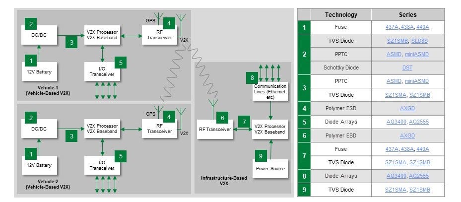
Figure 3: V2V and V2I Subsystems block diagram
Protecting the emergency call (eCall) subsystem
The emergency call feature in autonomous vehicles automatically contacts emergency services in the event of a serious accident or other emergency. This feature aims to improve safety and response time during critical incidents by providing timely and accurate information to emergency responders. Figure 4 details a block diagram for an eCall system.
The eCall subsystem, since it is for emergencies, is expected to be highly reliable. Protect the system with ceramic, surface mount AEC-Q200 Revision E fuses against overcurrent conditions. Keep ESD and other voltage transients from damaging the circuits by having TVS and ESD diodes in the I/O terminals and the wireless transceiver circuitry. Use AEC-Q101-qualified TVS diodes and diode arrays.
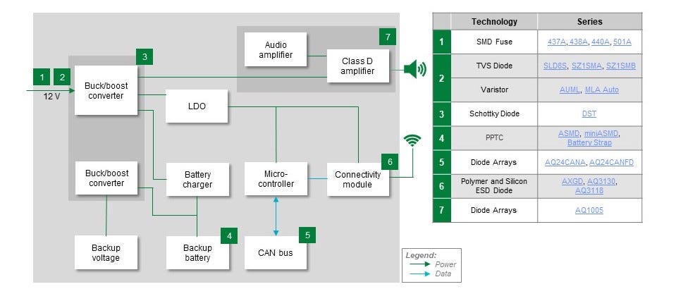
Figure 4: eCall subsystem block diagram
Protecting the smart Infotainment subsystem
The Smart infotainment subsystem integrates multiple technologies to provide both entertainment and information. It combines traditional in-car entertainment features with connectivity and internet capabilities to create an intelligent and user-friendly interface for drivers and passengers. Smart infotainment systems' features include multimedia entertainment, navigation and mapping, voice control, internet access, smartphone integration, and vehicle data.
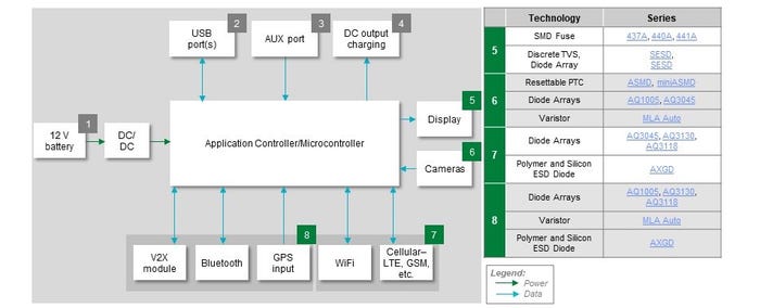
The smart infotainment subsystem, shown below in Figure 5, is as essential as the other subsystems. Thus, it should have the same level of protection. Use AEC-Q200 Revision E-qualified fuses for reliable overcurrent protection. Use AEC-Q101-qualified TVS diodes and diode arrays to protect the circuit blocks from transients and ESD.
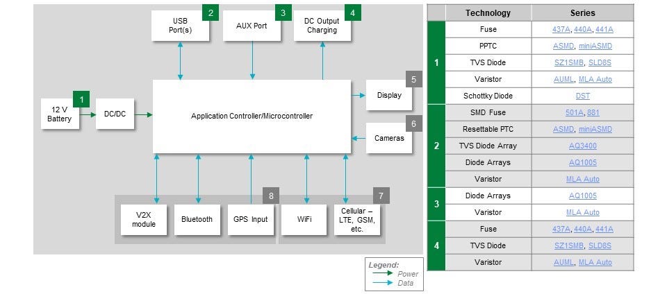
Figure 5: Smart infotainment subsystem block diagram (Above: Components 1 to 4; Below: 5 to 8)
Conclusion
A diverse selection of components is available to protect today's advanced automotive circuitry from electrical stresses. To save development time, take advantage of the expertise of the component manufacturer to get assistance with selection of the most cost-effective protection components. Be sure to use AEC-Q200 Revision E qualified fuses and resettable PPTCs as well as AEC-Q101 qualified TVS, ESD, and Schottky diodes to help accelerate compliance with quality and reliability standard requirements. Doing so will give the design team and manufacturer confidence that the board-level components will provide robust circuit protection to ensure highly reliable performance and long life.
For more information, see the Automotive Electronics Applications Guide and Supercharged Solutions for EV Charging Stations, courtesy of Littelfuse.
Referenced Standards
AEC-Q101 Rev-E: Failure Mechanism Based Stress Test Qualification for Discrete Semiconductors.
Automotive Electronics Council, March 1, 2021 (www.aecouncil.com)AEC-Q200 Revision-E: Stress Test Qualification for Passive Components.
Automotive Electronics Council, March 20, 2023 (www.aecouncil.com)
About the Author(s)
You May Also Like


