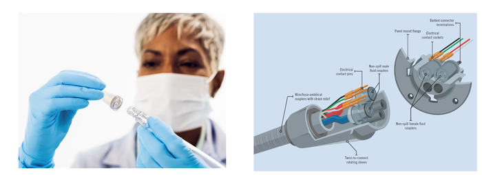
How to Get Fluid Coupling Design Right
Fluid management design can be tricky. You have to get a number of things right: flow rates, starting and stopping the flow, chemical compatibility, and more.
November 16, 2022

Design engineers often have dozens of technical and design issues to solve, and typically they don’t have a lot of time to solve them. There’s value in figuring out where to focus your efforts and where to collaborate with experts who understand—and have tackled—the challenges you need to address.
Any engineer who has designed a system involving fluid management knows it can be tricky. Flow rates, the ability to start and stop flow without issues, chemical compatibility, and more can affect overall product performance, ease of use, reliability, and maintenance.
Design News spoke to two engineers from CPC, a St. Paul, Minn.-based global connection technologies company. Matt Larsen, senior applications engineer, and Ingo Mohr, applications engineer III, explained how connectors influence overall system functionality.
Design News: What’s one of the most common issues you see around fluid management during the design process?
Matt Larsen: Fluid management is found in a huge range of equipment these days from medical devices to liquid-cooled high-performance computing equipment to large-format printers. The list goes on, but too often equipment is designed with connectors as an afterthought. These critical points of connection can—and often do—have a large impact on performance.
Understanding the basics around connection technologies is helpful, but partnering with an expert can be a time- and hassle-saving option.

DN. What fluid system fundamentals should design engineers keep in mind?
Matt Larsen: For large, complex systems, ensure all components can handle the flow rates throughout. For example, in liquid-cooled high-performance computing, flow rates are typically low at the server—say 0.5 l/min—and much higher at a cooling distribution unit, up to 70 l/min. Actual-use flow rates that exceed the connector’s maximum flow rate capacity can lead to seal failure or accelerated part degradation.
Also, every component in a fluid circuit presents resistance: filters, pumps, and connectors. You need to calculate the allowable pressure loss/drop across the system and understand the effects of each addition to the fluid path.
Ingo Mohr: With connectors, flow rate, valve type, and connector size affect pressure drop. Depending on the device or system, multiple connector types and sizes could be operating in parallel and series. That’s why it’s important to factor them into overall fluid system planning and to calculate pressure drop throughout the system.
DN. How do you calculate pressure drop?
Matt Larsen: The following equations (imperial and metric) calculate the pressure drop for a given flow rate through a quick disconnect (QD) connector:
Imperial formula: Q=Cv∙∆pSG
Q = volumetric flow rate in gallons per minute
Cv = flow coefficient of the connector
ΔP = pressure drop in PSI (Δ between the upstream pressure and the downstream pressure)
SG = specific gravity of the fluid
Valve flow coefficient (Cv) is a valve's capacity for a liquid or gas to flow through it. It is defined as the volume of water (in U.S. gallons) at 60°F that will flow through a valve per minute with a pressure drop of 1 psi across the valve.
DN: In addition to pressure drop, what other factors should design engineers keep in mind?
Ingo Mohr: Chemical compatibility between fluids and all components in the connector: valves, seals, springs, and the connector body itself. Also environmental exposures including temperature and cleaning solutions, and handling scenarios. In some applications, you need to think about whether connectors should be disposable or reusable.
Matt Larsen: In terms of exposures, consider how the fluid system will react outside of the day-to-day operation. For example, equipment that ships with fluid can off-gas if it’s an open system or undergoes significant increases in pressure for a closed system exposed to external pressures—think shipment by airplane—or high temperatures in transit. And for overall system functioning, don’t forget to assess normal operating pressure along with minimum and maximum pressure limits.
Ingo Mohr: From a usability standpoint, it’s useful to know the size and configuration of the connector needed for real-life operation. Do you have tight spaces where elbows or swivel joints are required so the connectors fit? Can you employ ease-of-use factors like ergonomic designs to facilitate one-handed operation, which is beneficial when you’re connecting and disconnecting tubing and maintaining a system?
Matt Larsen: And one thing that many design engineers aren’t aware of is that connectors of the same size can deliver significantly different flow performance. For example, a newer 1/8-inch quick disconnect showed a 23% better flow rate (flow coefficient: CV=0.37) than other currently available 1/8-inch connectors. It reduced pressure drop through the connector by ~34%, lowering the system burden.
Ingo Mohr: In certain applications, you need to consider the level of tolerance for liquid escape at disconnection. Seals, valve type and overall connector design impact the level of fluid present at disconnection (see Figure 1).
Fig. 1 —Valve and Seal Considerations |
Straight-through connectors (aka non-valved) |
Single shut-off valve |
Double shut-off valves |
Flush-face valves |
Seal type |
We see this in liquid-cooled electronics. Expensive electronics and fluid leaks don’t mix well, so engineers often specify connectors that reduce or stop the flow. Certain dripless or non-spill connectors feature flush-face valves that allow no more than a coating of fluid on valve surfaces after disconnect, which is very desirable in many applications.
Matt Larsen: Robust connectors deliver long-term, leak-free performance. There is a range of tests that apply to connectors so design engineers can better gauge what kind of product they’re getting. (See Fig. 2). Leak, flow rate, and force-to-connect tests, for example, can supply a lot of great information on what to expect at connection points. Design engineers can ask their connector partners for validation reports that specify test protocols and results.
Fig. 2 — Reliability testing Types of testing include: |
Pressure decay test |
Helium leak test |
Bubble leak test |
Elevated temperature burst test |
Creep rupture test |
Flow rate test |
Disconnect under flow |
Cycle testing |
Connect force testing |
DN: Based on your experience, why else should design engineers rely on specialists when it comes to connection technologies?
Matt Larsen: For many engineers, moving fast is often considered the enemy of smooth outcomes, but we’re all being asked to design smarter and launch faster.
Collaborating with a connector specialist allows you to quickly tap into deep understanding and experience regarding the impact of connector design (geometries, materials, chemical compatibility, etc.) on flow rate, durability, overall function, and more. We find that design engineers appreciate the ability of experts like CPC to solve engineering challenges in real time.
Also, parallel path development allows product or systems engineers to focus on other tasks while the connector engineers address that part of the project.
Ingo Mohr: Connector engineers ask probing questions on specific applications and understand fluid management goals, resulting in faster, more efficient collaboration. At our company, most engineers have not only fluid management expertise but a background in other categories (e.g., industrial, automotive, medical device) so they’re familiar with a broad range of end-use applications.
DN: So, you think design engineers’ jobs might be easier if they better appreciated how connectors impact fluid management performance?
Matt Larsen: Sometimes design engineers don’t realize how significant connector impact can be until the product or process is up and running. Flow rate, chemical compatibility, temperature, pressure, and even shipping conditions can affect critical points of connection. Depending on the application, product performance can be compromised if the right connectors aren’t in place. Connector experts can help you avoid these unintended consequences.
Ingo Mohr: If fluid system planning is not part of the early product or system development, engineers risk not achieving the flow rates and performance they planned. The good news is that design engineers don’t have to figure out the impact of connectors. A connector expert can provide accurate, useful solutions based on your needs. Also, rather than taking the time to sift through and assess thousands of potential components, an expert can quickly direct you to the option that’s going to best suit your requirements—and reassure you that you’ve made good connection technology choices for your specific application.
About the Author(s)
You May Also Like


