How to Build a Better Depalletizing Application
With precise motion control and 3D vision systems, depalletizing systems can offer decreased downtime, flexibility, and a smaller footprint.
October 18, 2023

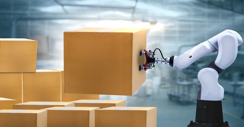
One specialized robot application is depalltizing. Robotic depalletizing systems for manufacturing plants and distribution facilities require precise motion control. Robots can use vision to find and locate haphazard material by using a vision system that can determine where the objects are. In a system, a wide range of products can be depalletized.
While the objects getting depalletized can vary, the core features and requirements remain the same. We reached out to Nick Longworth, a business consultant for industrial robotics at SICK, to get his views on how to build a successful depalletizing system.
Design News: Who are the users of a depalletizing solution?
Nick Longworth: Depalletizing is a cross-industry application. It can be used by just any user who has processes that rely on palletized products. The appearance just looks a little different depending on the user but many of the core features and requirements remain the same. For instance, a foundry may be depalletizing castings while a warehouse is depalletizing a mixed SKU pallet of boxes or anywhere in between. There may be some application-specific needs that are required for each, but many of the core challenges remain the same.
DN: Explain the challenges involved in designing a depalletizing robotic solution.
Nick Longworth: How do you increase throughput while remaining safe, reliable, small footprint, and cost-effective? (Good, fast, and cheap, can we have all three?). This is the challenge of any robotic solution design, including depalletizing, and can be contradictory in nature. The challenge becomes how to balance them for that particular application/customer. Using the right technology for the application helps significantly in this effort. When considering using 3D vision, especially with SICK PLB, there are several key questions we ask that help identify challenges:
What is the placement accuracy?
What is the pick to pick cycle time?
What are the budget requirements?
What are the item variations for localization?
What is the required pick rate?
What is the ease of use requirement?
The answers to this help to determine if 3D vision (SICK PLB) is a fit for an application along with allowing SICK to be a consultant to the application. SICK will often make recommendations on best practices and partners for other areas of the robotic system to help accommodate challenges in gripping, speed, etc.
DN: Explain the importance of a 3D vision system, specifically the need for “3D” vision.
Nick Longworth: For any robotic-based material handling system, there must be some method of “feeding” workpieces/items into the system for manipulation. Depending on the application and the process being automated, this could be a mechanical automation system, human loading, vision, etc. 3D vision is just a version of a feeding system in these operations and like all other feeding options has its benefits and detractions. These factors determine its importance, or non-importance, to a potential user:
Benefits
Increases Flexibility
3D vision enables dynamic picking operations where a robot can find/pick items regardless of position, size, etc.
Reduces Downtime/Increased Throughput
3D vision is less rigid compared to other feeding techniques that rely more on hard automation setups. Change over time between items is very minimal with 3D vision. The vision system simply recognizes the next items to be picked, no tooling change or setup is required to feed the new items. It will have much better ROI for low volume, high mix operations.
Better Ergonomics
3D vision enables humans to be removed from the feeding process other than loading a pallet/bin into the workspace. This reduces the ergonomic impact of production/fulfillment process on humans.
Decreases footprint
3D vision allows for the robot to interact directly with the shipped package in depalletizing. Additional equipment for feeding the robot such as conveyors is not needed which reduces the footprint of the robotic system.
Detractions
Complexity
3D vision is more complex than other techniques. It has a learning curve that may not exist with other hard automation techniques. Products like SICK PLB have a configurable, easy-to-use interface, but they will always be more complex on the technology scale compared to something like a conveyor-based feeder.
Neutral Comments
Cost
As 3D vision costs have come down, it is interesting that when considering the total cost of ownership (and even initial cost in some cases), the cost of different feeding systems is relatively equal in this day and age.
Overall, 3D vision is a tool in the toolbox of handling applications in robotics. Its importance is in completing a portfolio of feeding options that, in combination and careful selection for the use case, will enable users to reach the holy grail: lights out operations.

DN: What are the components involved in the vision system?
Nick Longworth: There are several components:
3+ axis robot
The first component involved in the vision system is always the robot. The robot guidance vision system is a paperweight without the robot being available to use the guidance system. Typically, a 5 or 6-axis robot is used in depalletizing, but it is not required to operate the vision system. Depending on the application, as little as three axes (XYZ motion) are required to use 3D vision technology.
Camera system
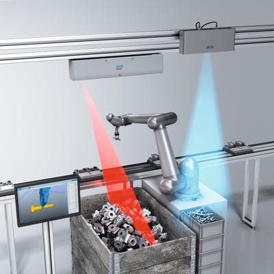
This is the imager that provides the 2D image/3D point cloud of the pickable workspace. This can be robot-mounted or fixed-mounted and must have the optical technology to image the volume of view requirement for the application design.
Robot Guidance Controller/Software
Depending on the complexity of the application, a smart camera or external controller with the robot guidance software loaded may be needed for processing. Smart cameras can complete all processing on board, but they are typically slower and feature-limited. An external controller will be able to process an application faster with more advanced features and capabilities, but will typically be more costly and require more wire routing.
Alignment Sphere/Cone
This is the fiducial used to teach the robot’s coordinate system to the vision system. It is mounted to the robot (fixed-mounted camera) or placed in the workspace (robot-mounted camera) and the robot is run through an automated routine to complete the alignment process.
Accessories (Cables, power supplies, etc. These will differ from system to system)
DN: How does the solution deal with different types of pallets and different sizes of objects?
Nick Longworth: SICK PLB’s depalletizing focused algorithms provide model-less operation. This means the algorithms do not need to know the item that they are imaging (size, type, etc.). As long as the algorithm is configured to know the primitive that it is being tasked to locate (box, bag, etc.). Given the application is set up with a camera that has a volume of view that encompasses the workspace and a software configuration that supports the picking needs (i.e. items are in the search volume), the system will localize and develop pick data (path plan, etc.) for collision-free picking.
SICK PLB can provide algorithms with rule-based and deep-learning functionality.
A rule-based depalletizing algorithm can naturally be model-less for varied primitive object sizes (boxes for instance) as they localize based on the shape of the point cloud. Larger objects in the point cloud end up with larger surfaces and larger localizations. A range of acceptable sizes can be set. This is basically just playing connect the dots with configurable rules for how much distance/angle is allowed between the dots. It generally requires a high accuracy imager to be successful.
A deep learning depalletizing algorithm uses a transfer learning concept. The neural network operates on the 2D image for the segmentation of objects and then uses the segmented image to position the localizations into the 3D point cloud for picking. The transfer learning concept means the neural network is pretrained to understand in general what a box is rather than a specific box type. This allows the neural network to identify and localize objects regardless of size and type without re-training the network. Typically, this transfer network will cover 80-90% of requirements in the application with some light retraining of edge cases (50-100 images) required for robust performance.
DN: What are the maintenance challenges for this solution?
Nick Longworth: The core 3D vision system has very few moving parts so maintenance is typically a nonissue beyond standard cleaning procedure. Automated alignment procedures allow quick recovery (as little as one minute) of the system if cleaning requires the camera to be unmounted or if the robot encounters an issue that requires realignment.
MTBF typically is over 150,000 hours of use (active imaging time, not robot operation time) which is limited by the projectors on the camera.
DN: What are the safety issues involved and how are they addressed?
Nick Longworth: Like any robot application, a Risk Assessment must be performed to address the hazards associated with each task a person performs around the system. You need to address hazards from the robot itself, automation in the environment (e.g. conveyors), and hazards in the environment (e.g. forklifts) where the system is installed. With the same robot application installed in different locations, the locations themselves can have different hazards. That’s why it is important to do a Risk Assessment for each location. SICK can help customers with Risk Assessments and provide training on how to do them.

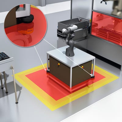
Safeguarding solutions for these types of applications can vary depending on the type of robot used (collaborative vs non collaborative) and how the pallets are put into place (e.g. forklift or conveyor). With collaborative robots, typical guarding involves using safety scanners like SICK’s microscan3 and nanoscan3 to slow the robot down when people get close and stop the robot if it gets too close. Collaborative robots with safe speed and force monitoring can stop when a person comes into contact with it. However, you usually want this to only occur when the robot is moving at a slow speed. Also, you never want the robot to come into contact with someone’s more sensitive body parts like the head and neck. This is why the use of safeguarding devices is needed even for collaborative robots. SICK has developed a safety package specifically for different robot manufacturers that provides a complete safety solution using scanners and safety controls called sBot. SICK’s sBot application package can even use the robot’s teach pendant to program the SICK safety scanner for some robot controllers. We also use SICK’s new 3D safety vision sensor, safevisionary2, to protect all the way around the top of this robot to prevent the robot from running if someone's head gets too close to the robot. Safeguarding non-collaborative robots usually involves hard guarding, gate interlocks, safety scanners, and light curtains.
Some palletizing/depalletizing applications use manual and automatic forklifts to load and unload pallets. This can be a challenging application to safeguard because you need to allow the forklift to enter the shared space with the robot, drop or pick up the load, leave, and then you want the robot to start back up again. Lucky Sick has developed a safety system called IVAR that can safely detect the difference between a person and a forklift or AGV. SICK microscan3 and nanscan3 safety scanners have special safety-rated fields that can detect the size of an object at different distances. We can use these contour fields to detect that a forklift is entering the shared space and mute the appropriate safeguards. This allows a forklift driver to enter the shared space, drop off the pallet, leave the area, and the robot can automatically begin picking parts without any driver intervention.
If pallets or boxes are entering the robot area on a conveyor, SICK has a number of solutions to allow them to enter but prevent people from entering the area. SICK’s deTem4 AP LT multi-beam light grid is a drop-in muting solution. The light grid comes with the muting sensors and mounting arms preassembled and ready to mount. Sick’s C4000 Fusion is a horizontally mounted light curtain that uses pattern recognition to determine the difference between a person and a pallet without the need for muting sensors. If boxes are entering the area then SICK’s deTec4 light curtain with smart box detection is the right solution. It will only allow boxes to enter. Anything else with trip the light curtain.
DN: How can throughput be increased (faster robots) without compromising safety?
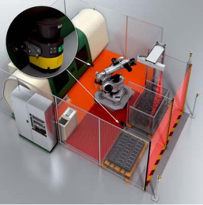
Nick Longworth: You can have the 2 bays or pick points for the robot to work in. This way the robot can always be picking or dropping packages/parts. The robot can work in one area while an operator can load or unload from the other area. Safeguarding can be added to make sure the robot does not enter into the area that the operator is in. Below is an example of this type of application. The light curtains can detect when an operator or forklift enters the different pallet areas. Many robots today can safely know their own position and report it a safety PLC like Sick Flexisoft over Ethernet IP CIP Safety. The safety PLC can then let the robot continue to run as long as the operator does not enter the pallet area it is working in.

Using the systems mentioned above can also help increase production. The sBot and IVAR safety solutions can allow the robot to automatically resume operation when operators and forklifts to enter the robot-shared space and then leave. These do not require any manual resets by the operators. This saves time and ensures the robots continue to run.
The sBot safety solution was also designed with increased throughput in mind. It allows the robot to run faster until someone enters into the robot area. Then it slows the robot down to reduce the risk to the person. If the person gets too close it can stop the robot. When the person leaves the robot area, the robot can continue at high speed again. This keeps the robot running as much as possible when people are present.
DN: How can the footprint be reduced without compromising safety?
Nick Longworth: Reducing a robot cell's footprint while maintaining safety involves careful planning and design. Here are some strategies:
Compact Robot Models: Use smaller and more efficient robot models that can perform the required tasks without compromising safety.
Layout Optimization: Carefully plan the layout of equipment and workstations to minimize wasted space and ensure efficient robot movements.
Collaborative Robots: Implement collaborative robots that can work alongside humans, saving space compared to traditional industrial robots.
Vertical Integration: Utilize vertical space by stacking or mounting equipment and materials to make the most of the available floor area.
Modular Workstations: Design workstations and equipment to be modular and easily reconfigurable, allowing for flexible use of space.
Safety Barriers: Use advanced safety systems such as Sick’s microscan3 laser scanners or deTec4 light curtains and a robot with safe position & speed monitoring to reduce the need for physical safety barriers, creating a more compact workspace.
Automated Material Handling: Implement automated material handling systems to optimize space usage and reduce the need for manual material transport.
Safety Sensors: Utilize safety sensors (e.g. nanoscan3) and vision systems (e.g. Safevisionary2) to allow robots to operate in closer proximity to human workers safely.
Lean Manufacturing: Apply lean manufacturing principles to streamline processes and minimize unnecessary equipment and space.
Simulation Software: Use robot simulation software to test and optimize robot cell layouts before implementation.
Remember that ensuring safety is paramount, so it's crucial to conduct a risk assessment and follow safety standards and guidelines throughout the design and implementation process.
About the Author(s)
You May Also Like


.jpg?width=300&auto=webp&quality=80&disable=upscale)


